


CHAPTER 4: Installation
27
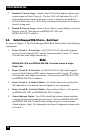
4.3. Serial SetUp Port Connection
The Outlet Managed PDU’s SetUp Port is a female, RJ45 RS232 connector, wired
in a DCE conguration. In the default state, the Setup port is congured for 9600
bps, no parity, 8 data bits, 1 stop bit. The Setup Port can be connected to either an
external modem or a local PC, but not both items at the same time. Appendix A
describes the Setup Port interface.
4.3.1. Connecting a Local PC
Use the DX9F-DTE-RJ Adapter supplied with the unit to connect your PC COM port
to the Outlet Managed PDU’s Setup Port. Make certain that the Serial Port Mode is
set to "Normal" as described in Section 5.8.
4.3.2. Connecting an External Modem
When connecting directly to an external modem, use the optional DX9M-RJ-KIT
(not included) to connect your external modem to the Outlet Managed PDU’s Setup
Port. Make certain that the modem is initialized at the same default parameters as
the Outlet Managed PDU Setup Port and that the Outlet Managed PDU Serial Port
Mode is set to "Modem" as described in Section 5.8.
4.4. Connecting the Network Cable
The Network Port is an RJ45 Ethernet jack, for connection to a TCP/IP network.
Connect your 100Base-T cable to the Network Port. Note that the Outlet Managed
PDU includes a default IP address (192.168.168.168) and a default subnet mask
(255.255.255.0.) When installing the Outlet Managed PDU in a working network
environment, it is recommended to dene network parameters as described in
Section 5.9.
4.5. Rack Mounting
To install an Outlet Managed PDU in your equipment rack, attach the L-Brackets
included with the unit and then mount the unit in a vacant space in your rack.
This completes the Outlet Managed PDU installation instructions. Please proceed to
the next Section for instructions regarding unit conguration.