


E6581160
71
8
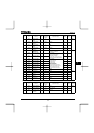
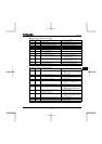
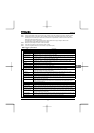
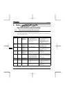
Note 1. Capacity is calculated at 220V for the 240V models, at 440V for the 500V models and at 575V for the 600V models.
Note 2. Indicates rated output current setting when the PWM carrier frequency (parameter F300) is 4kHz or less. When
exceeding 4kHz, the rated output current setting is indicated in the parentheses. It needs to be further reduced for
PWM carrier frequencies above 12 kHz.
The rated output current is reduced even further for 500V models with a supply voltage of 480V or more.
The default setting of the PWM carrier frequency is 12kHz.
Note 3. Maximum output voltage is the same as the input voltage.
Note 4. ±10% when the inverter is used continuously (load of 100%).
Note 5. If you are using 600V model, be sure to connect an input reactor (ACL).
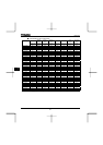
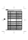
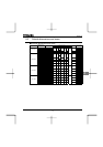
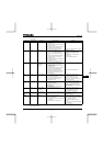
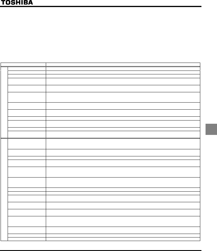
Q Common specification
Item Specification
Control system Sinusoidal PWM control
Rated output voltage Adjustable within the range of 50 to 600V by correcting the supply voltage (not adjustable above the input voltage)
Output frequency range 0.5 to 500.0Hz, default setting: 0.5 to 80Hz, maximum frequency: 30 to 500Hz
Minimum setting steps of
frequency
0.1Hz: analog input (when the max. frequency is 100Hz), 0.01Hz: Operation panel setting and communication
setting.
Frequency accuracy Digital setting: within ±0.01% of the max. frequency (-10 to +60°C)
Analog setting: within ±0.5% of the max. frequency (25°C ±10°C)
Voltage/frequency
characteristics
V/f constant, variable torque, automatic torque boost, vector control, automatic energy-saving, dynamic automatic
energy-saving control, PM motor control. Auto-tuning. Base frequency (25 - 500Hz) adjusting to 1 or 2, torque boost
(0 - 30%) adjusting to 1 or 2, adjusting frequency at start (0.5 - 10Hz)
Frequency setting signal Potentiometer on the front panel, external frequency potentiometer (connectable to a potentiometer with a rated
impedance of 1 - 10kΩ), 0 - 10Vdc (input impedance: VIA/VIB=30kΩ, 4 - 20mAdc (Input impedance: 250Ω).
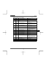
Terminal board base
frequency
The characteristic can be set arbitrarily by two-point setting. Possible to set individually for three functions: analog
input (VIA and VIB) and communication command.
Frequency jump Three frequencies can be set. Setting of the jump frequency and the range.
Upper- and lower-limit
frequencies
Upper-limit frequency: 0 to max. frequency, lower-limit frequency: 0 to upper-limit frequency
PWM carrier frequency Adjustable within a range of 2.0 to 16.0Hz (default: 12kHz).
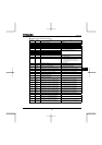
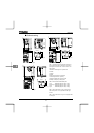
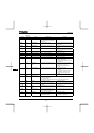
Principal control functions
PID control Setting of proportional gain, integral gain, differential gain and control wait time. Checking whether the amount of
processing amount and the amount of feedback agree.
Acceleration/deceleration
time
Selectable from among acceleration/deceleration times 1, 2 and 3 (0.0 to 3200 sec.). Automatic
acceleration/deceleration function. S-pattern acceleration/deceleration 1 and 2 and S-pattern adjustable. Control of
forced rapid deceleration and dynamic rapid deceleration
DC braking Braking start-up frequency: 0 to maximum frequency, braking rate: 0 to 100%, braking time: 0 to 20 seconds,
emergency DC braking, motor shaft fixing control
Dynamic braking Control and drive circuit is built in the inverter with the braking resistor outside (optional).
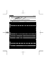
Input terminal function
(programmable)
Possible to select from among 66 functions, such as forward/reverse run signal input, jog run signal input, operation
base signal input and reset signal input, to assign to 8 input terminals. Logic selectable between sink and source.
Output terminal functions
(programmable)
Possible to select from among 58 functions, such as upper/lower limit frequency signal output, low speed detection
signal output, specified speed reach signal output and failure signal output, to assign to FL relay output, open
collector output and RY output terminals.
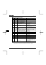
Forward/reverse run The RUN and STOP keys on the operation panel are used to start and stop operation, respectively. The switching
between forward run and reverse run can be done from one of the three control units: operation panel, terminal
board and external control unit.
Jog run Jog mode, if selected, allows jog operation from the operation panel or the terminal board.
Preset speed operation Base frequency + 15-speed operation possible by changing the combination of 4 contacts on the terminal board.
Retry operation Capable of restarting automatically after a check of the main circuit elements in case the protective function is
activated. 10 times (Max.) (selectable with a parameter)
Various prohibition
settings
Possible to write-protect parameters and to prohibit the change of panel frequency settings and the use of operation
panel for operation, emergency stop or resetting.
Regenerative power ride-
through control
Possible to keep the motor running using its regenerative energy in case of a momentary power failure (default:
OFF).
Auto-restart operation In the event of a momentary power failure, the inverter reads the rotational speed of the coasting motor and outputs
a frequency appropriate to the rotational speed in order to restart the motor smoothly. This function can also be
used when switching to commercial power.
Drooping function When two or more inverters are used to operate a single load, this function prevents load from concentrating on one
inverter due to unbalance.
Override function The sum of two analog signals (VIA/VIB) can be used as a frequency command value.
Operation specifications
Failure detection signal 1c-contact output: (250Vac-0.5A-cosφ=0.4)
<Continued overleaf>