


E6581160
13
2
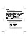
Wire size (See Note 4)
Voltage class
Capacity of
applicable
motor (kW)
Inverter model
Power circuit
(mm
2
) (Note 1.)
DC reactor
(optional) (mm
2
)
Braking resistor/
Braking unit
(optional) (mm
2
)
Earth cable
(mm
2
)
0.4 VFS11-4004PL 2.0 (2.0) 2.0 2.0 3.5
0.75 VFS11-4007PL 2.0 (2.0) 2.0 2.0 3.5
1.5 VFS11-4015PL 2.0 (2.0) 2.0 2.0 3.5
2.2 VFS11-4022PL 2.0 (2.0) 2.0 2.0 3.5
4.0 VFS11-4037PL 2.0 (2.0) 2.0 2.0 3.5
5.5 VFS11-4055PL 2.0 (2.0) 3.5 2.0 3.5
7.5 VFS11-4075PL 3.5 (2.0) 5.5 2.0 3.5
11 VFS11-4110PL 5.5 (2.0) 8.0 2.0 5.5
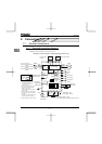
Three-phase
500V class
15 VFS11-4150PL 8.0 (5.5) 14 3.5 5.5
0.75 VFS11-6007P 2.0 2.0 2.0 3.5
1.5 VFS11-6015P 2.0 2.0 2.0 3.5
2.2 VFS11-6022P 2.0 2.0 2.0 3.5
4.0 VFS11-6037P 2.0 2.0 2.0 3.5
5.5 VFS11-6055P 2.0 2.0 2.0 3.5
7.5 VFS11-6075P 2.0 2.0 2.0 3.5
11 VFS11-6110P 3.5 3.5 2.0 3.5
Three-phase
600V class
15 VFS11-6150P 5.5 5.5 2.0 5.5
Note 1: Sizes of the wires connected to the input terminals R/L1, S/L2 and T/L3 and the output terminals U/T1,
V/T2 and W/T3 when the length of each wire does not exceed 30m.
The numeric values in parentheses refer to the sizes of wires to be used when a DC reactor is connected.
Note 2: For the control circuit, use shielded wires 0.75 mm
2
or more in diameter.
Note 3: For grounding, use a cable with a size equal to or larger than the above.
Note 4: The wire sizes specified in the above table apply to HIV wires (cupper wires shielded with an insulator
with a maximum allowable temperature of 75°C) used at an ambient temperature of 50°C or less.
Note 5: If there is a need to bring the inverter into UL compliance, use wires specified in Chapter 6.
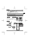
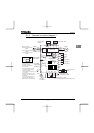
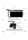
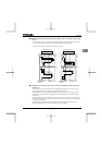
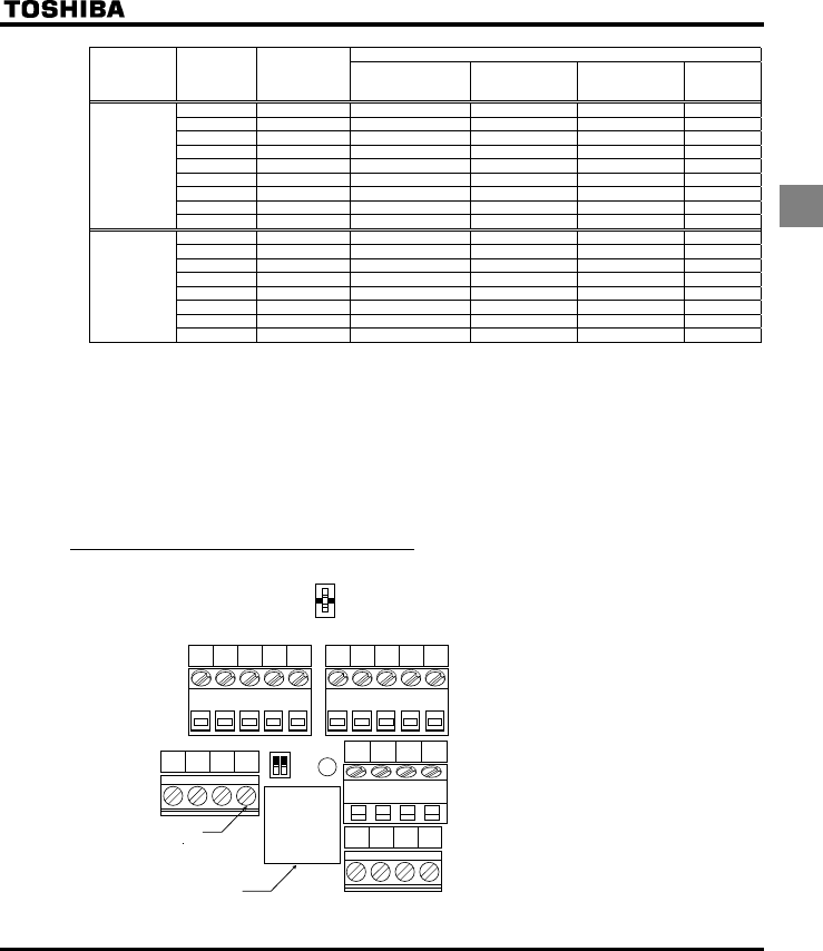
2.2.3 Control circuit terminals
P24
PP VIA VIB CC
PLC S1 S2 S3
FM VIA
PLC
SOURCE
SINK
SW1
OUT NO FM CC
FLA FLB FLC RY RC
F R RES CC
V
I
V
I
Optional connector
(RJ45)
M3 screw
(0.5N m)
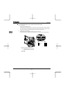
Factory default settings of slide switches
SW1: SINK (Negative) side (WN, AN type)
SOURCE (Positive) side (WP type)
FM: V side
VIA: V side
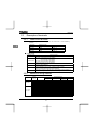
Wire size
Solid wire: 0.3 ∼ 1.5 (mm
2
)
Stranded wire: 0.3 ∼ 1.5 (mm
2
)
(AWG 22 ∼ 16)
Sheath strip length: 6 (mm)
Screwdriver: Small-sized flat-blade screwdriver
(Blade thickness: 0.4 mm or less,
blade width: 2.2 mm or less)
The control circuit terminal
board is common to all
equipment.