


E6581160
36
5
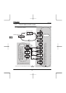
5. Monitoring the operation status
Refer to 4.1 about flow of monitor.
5.1 Status monitor mode
5.1.1 Status monitor under normal conditions
In this mode, you can monitor the operation status of the inverter.
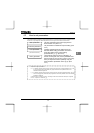
To display the operation status during normal operation:
Press the key twice.
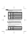
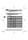
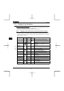
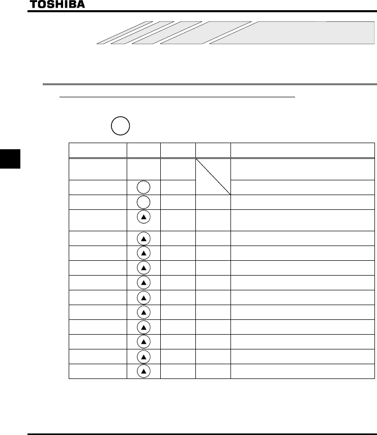
Setting procedure (eg. operation at 60Hz)
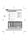
Item displayed
Key
operated
LED
display
Communic
ation No.
Description
.
The operation frequency is displayed (Operation at
60Hz). (When standard monitor display selection
H is set at 0 [operation frequency])
Parameter setting
mode
CWJ
The first basic parameter “CWJ” (history function)
is displayed.
Direction of
rotation
HTH
FE01
The direction of rotation is displayed.
(HTH: forward run, HTT: reverse run)
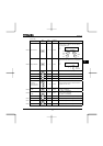
Operation
frequency
command
H
FE02
The operation frequency command value (Hz/free
unit) is displayed.
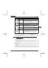
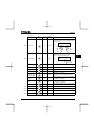
Load current E FE03
The inverter output current (load current) (%/A) is
displayed.
Input voltage
[
FE04 The inverter input (DC) voltage (%/V) is displayed.
Output voltage R FE05 The inverter output voltage (%/V) is displayed.
Torque SQ FE18 The torque (%) is displayed.
Torque current Y FE20 The torque current (%/A) is displayed.
Inverter load factor
N
FE27 The inverter load factor (%) is displayed.
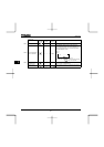
PBR cumulative
load factor
T
FE25
The cumulative load factor of the braking resistor
(%) is displayed.
Input power
k
FE29 The inverter input power (kW) is displayed.
Output power J FE30 The inverter output power (kW) is displayed.
Operation
frequency
Z FD00
The operation frequency (Hz/free unit) is
displayed.
(Continued overleaf)
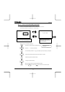
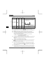
Note 1
Note 2
Note 3
MO
MOMO
MODE
DEDE
DE
MO
MOMO
MODE
DEDE
DE
MODE