


E6581160
46
6
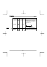
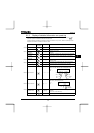
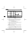
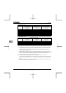
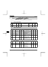
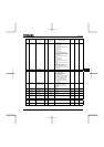
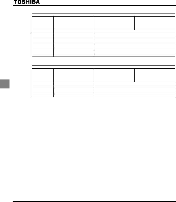
Three-phase 500V class
Combination of inverter and filter
Inverter Transmission noise
EN55011 Class A Group 1
Applicable filters
(Length of motor connecting cable:
Max. 5 m)
Transmission noise
EN55011 Class B Group 1
Applicable filters
(Length of motor connecting cable:
Max. 20 m)
Transmission noise
EN55011 Class A Group 1
Applicable filters
(Length of motor connecting cable:
Max. 50 m)
VFS11-4004PL With a built-in filter EMFS11-4015BZ
VFS11-4007PL With a built-in filter EMFS11-4015BZ
VFS11-4015PL With a built-in filter EMFS11-4015BZ
VFS11-4022PL With a built-in filter EMFS11-4025CZ
VFS11-4037PL With a built-in filter EMFS11-4025CZ
VFS11-4055PL With a built-in filter EMFS11-4047DZ
VFS11-4075PL With a built-in filter EMFS11-4047DZ
VFS11-4110PL With a built-in filter EMFS11-4049EZ
VFS11-4150PL With a built-in filter EMFS11-4049EZ
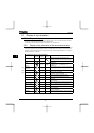
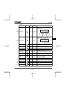
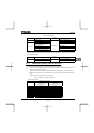
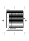
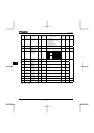
Single-phase 240V class
Combination of inverter and filter
Inverter Transmission noise
EN55011 Class A Group 1
Applicable filters
(Length of motor connecting cable:
Max. 5 m)
Transmission noise
EN55011 Class B Group 1
Applicable filters
(Length of motor connecting cable:
Max. 20 m)
Transmission noise
EN55011 Class A Group 1
Applicable filters
(Length of motor connecting cable:
Max. 50 m)
VFS11S-2002PL With a built-in filter EMFS11S-2009AZ
VFS11S-2004PL With a built-in filter EMFS11S-2009AZ
VFS11S-2007PL With a built-in filter EMFS11S-2009AZ
VFS11S-2015PL With a built-in filter EMFS11S-2016BZ
VFS11S-2022PL With a built-in filter EMFS11S-2022CZ
Note : For 600V models compliant with EU standards, contact your nearest Toshiba inverter distributor.
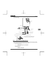
(2) Use shielded power cables, such as inverter output cables, and shielded control cables. Route the cables
and wires so as to minimize their lengths. Keep a distance between the power cable and the control cable
and between the input and output wires of the power cable. Do not route them in parallel or bind them
together, instead cross at right angle.
(3) Install the inverter and the filter on the same metal plate. It is more effective in limiting the radiation noise to
install the inverter in a sealed steel cabinet. Using wires as thick and short as possible, earth the metal plate
and the control panel securely with a distance kept between the earth cable and the power cable.
(4) Route the EMI filter input and output wires apart from each other.
(5) To suppress radiation noise from cables, ground all shielded cables through a noise cut plate.
It is effective to earth shielded cables in the vicinity of the inverter, cabinet and filter (within a radius of 10cm
from each of them). Inserting a ferrite core in a shielded cable is even more effective in limiting the radiation
noise.
(6) To further limit the radiation noise, insert a zero-phase reactor in the inverter output line and insert ferrite
cores in the earth cables of the metal plate and cabinet.