


E6581160
16
2
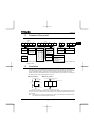
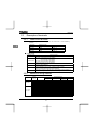
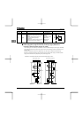
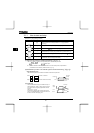
Terminal
symbol
Input/output Function
Electrical
specifications
Inverter internal circuits
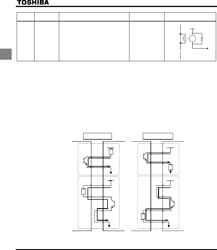
RY
RC
Output
Multifunction programmable relay contact
output.
Standard default settings detect and
output low-speed signal output
frequencies.
Multifunction output terminals to which two
different functions can be assigned.
250Vac-1A
(cosφ=1)
: at resistance load
30Vdc-0.5A
250Vac-0.5A
(cosφ=0.4)
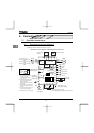
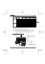
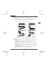
Q SINK (Negative) logic/SOURCE (Positive) logic (When the
inverter's internal power supply is used)
Current flowing out turns control input terminals on. These are called sink logic terminals. (Type: -AN/-WN).
The general used method in Europe is source logic in which current flowing into the input terminal turns it
on (Typ: -WP).
Sink logic is sometimes referred to as negative logic, and source logic is referred to as positive logic.
Each logic is supplied with electricity from either the inverter's internal power supply or an external power
supply, and its connections vary depending on the power supply used.
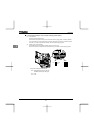
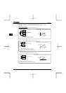
<Examples of connections when the inverter's internal power supply is used>
CC
NO
Source (Positive) logic
Inverter
P24
F
Programmable
controller
Common
Common
Output
Input
Input
24V
DC
Output
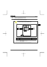
Sink (Negative) logic
F
CC
Common
Output
Input
24V
DC
Output
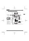
OUT
P24
24V
DC
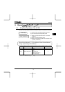
CC
NO
OUT
P24
24V
D
Input
Common
Inverter
Programmable
controller
Slide switch SW1:SINK Slide switch SW1:SOURCE
+24V
RY
RY
RC