


E6581160
10
2
2. Connection
2.1 Standard connections
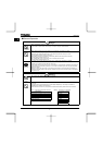
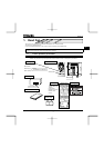
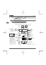
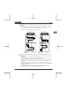
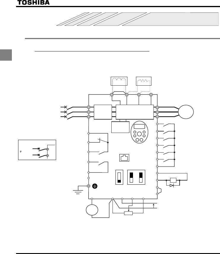
2.1.1 Standard connection diagram 1
This diagram shows a standard wiring of the main circuit.
MCCB
*1
R/L1
S/L2
T/L3
U/T1
V/T2
W/T3
I M
FLC
FLB
FLA
RY
RC
PLC
Motor
F
R
RES
S1
S2
S3
CC
P24
OUT
NO
CC
FM
PLC
CC
VIA
VIB
PP
+
+
-
-
P0
PA/+
PB PC/-
Meter
Voltage signal: 0-10V
(Current signal: 4-20mA)
External potentiometer (1~10kΩ)
(or input voltage signal across VIB-CC terminals: 0-10V)
Control
circuit
Operation panel
Protective function
activation output
Ry
VF-S11
Frequency
meter
(ammeter)
Power circuit
Noise
filter
DC reactor (DCL)
*2 (option)
Connector for
common serial
communications
Forward
Reverse
Reset
Preset-speed 1
Preset-speed 2
Preset-speed 3
Common
Braking resistor (option)
Standard connection diagram - SINK (Negative) (common:CC)
Low-speed
signal output
24Vdc input
7.5V-1mA
(or 4-20mA)
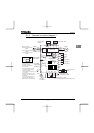
MCCB(2P)
R/L1
S/L2
Power supply
1 200~240V
-50/60Hz
Speed reach
signal output
I ISINK
SW1
SOURCE
FM
V
VIA
V
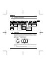
Main circuit power supply
240V class: three-phase 200-240V
-50/60Hz
500V class: three-phase 380-500V
-50/60Hz
600V class: three-phase 525-600V
-50/60Hz
*1: The T/L3 terminal is not provided
for single-phase models.
Use the R/L1 and S/L2 terminal
as input terminals.
*2: The inverter is supplied with the PO
and the PA/+ terminals shorted by
means of a shorting bar.
Before installing the DC reactor (DCL),
remove the bar.
*3: When using the OUT output terminal in
sink logic mode, short the NO and CC
terminals.
*4: If you are using a 600V model, be sure
to connect an input reactor (ACL).
*5: 600V models have no noise filter inside.
*3
*5