


E6581160
14
2
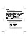
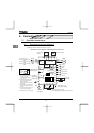
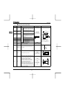
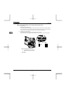
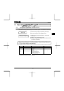
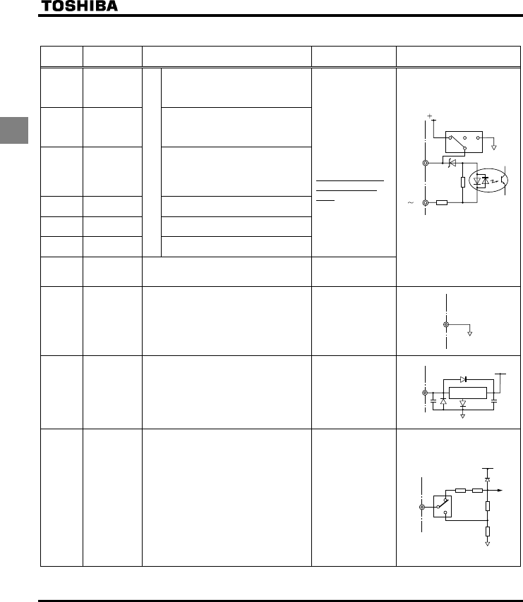
Q Control circuit terminals
Terminal
symbol
Input/output Function
Electrical
specifications
Inverter internal circuits
F Input
Shorting across F-CC causes
forward rotation; open causes slow-
down and stop. (When ST is always
ON)
R Input
Shorting across R-CC causes
reverse rotation; open causes slow-
down and stop. (When ST is always
ON)
RES Input
This inverter protective function is
disabled if RES are CC is connected.
Shorting RES and CC has no effect
when the inverter is in a normal
condition.
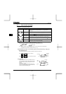
S1 Input
Shorting across S1-CC causes
preset speed operation.
S2 Input
Shorting across S2-CC causes
preset speed operation.
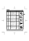
S3 Input
Multifunction programmable contact input
Shorting across S3-CC causes
preset speed operation.
No voltage
contact input
24Vdc-5mA or less
*Sink/Source/PLC
selectable using
SW1
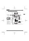
PLC
Input
(common)
External 24Vdc power input
When the source logic is used, a common
terminal is connected.
24VDC
(Insulation
resistance: DC50V)
Factory default setting
WN, AN type : SINK side
WP type : SOURCE side
CC
Common to
Input/output
Control circuit's equipotential terminal (3
terminals)
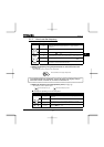
PP Output Analog power supply output
10Vdc
(permissible load
current: 10mA)
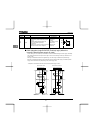
VIA Input
Multifunction programmable analog input.
Factory default setting: 0~10Vdc and
0~60Hz (0~50Hz) frequency input.
The function can be changed to
4~20mAdc (0~20mA) current input by
flipping the dip switch to the I position.
By changing parameter setting, this
terminal can also be used as a
multifunction programmable contact input
terminal. When using the sink logic, be
sure to insert a resistor between P24-VIA
(4.7 kΩ―1/2 W). Also move the VIA dip
switch to the V position.
10Vdc
(internal impedance:
30kΩ)
4-20mA
(internal impedance:
250Ω)
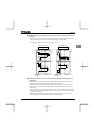
CC
PLC
4.7K
24V
SOURCE
SW1
PLC
SINK
820
F
S3
PP
0.47µ
+24V
conversion
Voltage
+5V
15k
15k
250
300
VIA
VIA
V
I