


E6581160
37
5
(Continued)
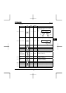
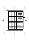
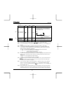
Item displayed
Key
operated
LED
display
Communic
ation No.
Description
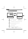
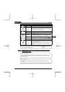
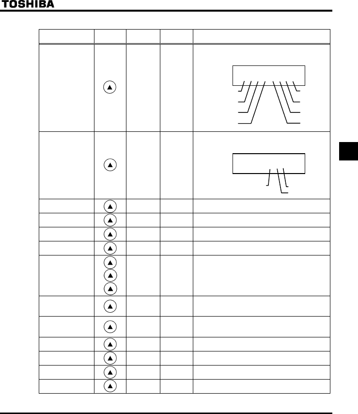
Input terminal
}}}ii}ii
FE06
The ON/OFF status of each of the control signal
input terminals (F, R, RES, S1, S2, S3, VIB and
VIA) is displayed in bits.
ON:
OFF: _
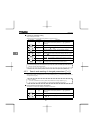
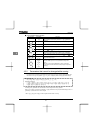
Output terminal
0 }ii
FE07
The ON/OFF status of each of the control signal
output terminals (RY, OUT and FL) is displayed in
bits.
ON:
OFF: _
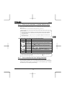
CPU1 version
X
FE08 The version of the CPU1 is displayed.
CPU2 version
XY
FE73 The version of the CPU2 is displayed.
Memory version
XG
FE09 The version of the memory mounted is displayed.
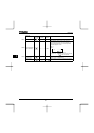
PID feedback F FE22
The PID feedback value is displayed. (Hz / free
unit)
Frequency
command value
(PID-computed)
D FE15
The PID-computed frequency command value is
displayed. (Hz / free unit)
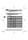
Integral input
power
k FE76
The integrated amount of power (kWh) supplied to
the inverter is displayed.
(0.01=1kWh, 1.00=100kWh)
Integral output
power
J FE77
The integrated amount of power (kWh) supplied
from the inverter is displayed.
(0.01=1kWh, 1.00=100kWh)
Rated current
C
FE70 The rated current of the inverter (A) is displayed.
Past trip 1
QE ⇔
FE10 Past trip 1 (displayed alternately)
Past trip 2
QJ ⇔
FE11 Past trip 2 (displayed alternately)
Past trip 3
QR ⇔
FE12 Past trip 3 (displayed alternately)
(Continued overleaf)
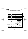
0 }ii
RY-RC
FL
OUT-NO
Note 6
Note 6
Note 7
Note 7
Note 4
Note 5
}}}ii}ii
VIA
VIB
S3
S2
F
R
RES
S1
Note 7