


E6581160
42
5
(Continued)
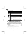
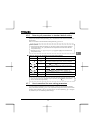
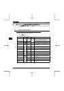
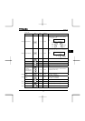
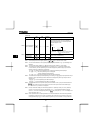
Item displayed
Key
operated
LED
display
Communic
ation No.
Description
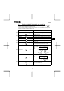
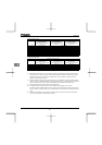
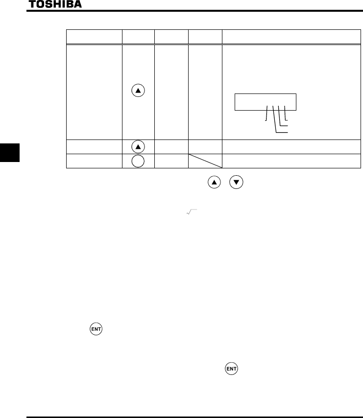
Parts replacement
alarm information
m }}}i FE79
The ON/OFF status of each of the cooling fan,
circuit board capacitor, main circuit capacitor of
parts replacement alarm or cumulative operation
time are displayed in bits.
ON:
OFF: _
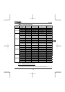
Cumulative
operation time
V FE14
The cumulative operation time is displayed.
(0.01=1 hour, 1.00=100 hours)
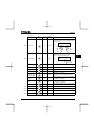
Default display
mode
QR The cause of the trip is displayed.
Note 1: Items displayed can be changed by pressing or key in the each monitor mode.
Note 2: You can switch between % and A (ampere)/V (volt), using the parameter H (current/voltage unit
selection).
Note 3: The input (DC) voltage displayed is 1
2
times as large as the rectified d.c. input voltage.
Note 4: The number of bars displayed varies depending on the setting of H (analog input/logic input
function selection). The bar representing VIA or VIB is displayed only when the logic input function is
assigned to the VIA or VIB terminal, respectively.
If H = 0: Neither the bar representing VIA nor the bar representing VIB is displayed.
If H = 1 or 2: The bar representing VIA is not displayed.
The bar representing VIB is displayed.
If H = 3 or 4: Both the bar representing VIA and VIB are displayed.
Note 5: The number of bars displayed varies depending on the setting of H (logic output/pulse train output
selection). The bar representing the OUT-NO terminal is displayed only when logic output function is
assigned to it.
If H = 0: The bar representing OUT-NO is displayed.
If H = 1: The bar representing OUT-NO is not displayed.
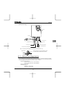
Note 6: The integrated amounts of input and output power will be reset to zero, if you press and hold down the
key for 3 seconds or more when power is off or when the input terminal function CKWH (input
terminal function: 51) is turned on or displayed.
Note 7: Past trip records are displayed in the following sequence: 1 (latest trip record) ⇔2⇔3⇔4 (oldest trip
record). If no trip occurred in the past, the message “PGTT” will be displayed. Details on past trip
record 1, 2, 3 or 4 can be displayed by pressing the key when past trip 1, 2, 3 or 4 is displayed. For
more information, see 5.1.2.
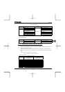
Note 8: Parts replacement alarm is displayed based on the value calculated from the annual average ambient
temperature, the ON time of the inverter, the operating time of the motor and the output current ( load
factor) specified using H. Use this alarm as a guide only, since it is based on a rough estimation.
m }}}i
Cooling
fan
Cumulative
operation time
Control circuit board capacitor
Main
circuit
capacitor
Note 8
Note 9
MO
MOMO
MODE
DEDE
DE