


Greensmaster 1000/1600
Page 6 – 13
Wheels and Accessories
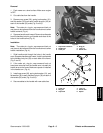
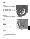
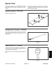
Kickstand
1. Cap screw
2. Cap screw
3. Lock washer
4. Spring bracket
5. Extension spring
6. Cap screw
7. Spring retainer
8. Kickstand
9. Flat washer
10. Lock nut
11. Spacer
12. Flange lock nut
Figure 14
1
2
3
4
5
6
7
8
9
10
11
12
9
FRAME
NOTE THE POSITION
OF THE STOP
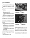
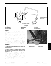
Removal
1. Park mower on a level surface. Make sure the en-
gine is OFF.
2. Pivot kickstand up against the handle and hold
there.
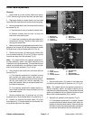
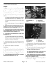
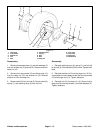
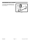
3. Use a pliers to remove the extension spring from the
spring retainer (Fig. 15).
4. Remove both lock nuts (10), flat washers (9), cap
screws (1), and spacers (11) from the kickstand (8) and
frame. Remove kickstand from the frame (Fig. 14).
Installation
1. Make sure mower is parked on a level surface and
the engine is OFF.
2. Position kickstand (8) inside the mower frame. In-
sert capscrews (1) through the frame, spacers (11), and
kickstand (Fig. 14).
3. Secure cap screws (1) with flat washers (9) and lock
nuts (10). Tighten fasteners (Fig. 14).
4. Pivot kickstand up against the handle and hold
there. Use a pliers to reinstall the extension spring to the
spring retainer (Fig. 15).
1. Kickstand
2. Extension spring
3. Spring retainer
4. Cap screw
Figure 15
3
4
1
2
Wheels and
Accessories