


Greensmaster 1000/1600 Traction and Reel Drive SystemsPage 4 – 25
Differential Assembly and Pulley
Removal
1. Park mower on a level surface. Make sure engine
is OFF. Remove high tension lead from the spark plug.
2. Lower handle to allow clearances for the removal of
the bearing and flangettes from the differential axle and
the differential assembly from the countershaft housing
(see Handle in the Adjustments section of Chapter 6 –
Wheels and Accessories).
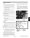
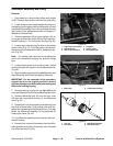
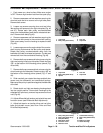
3. Remove capscrews (39) and lock washers (40) se-
curing rear and front box covers (38 and 39) to the coun-
tershaft housing (1). Pull covers from housing (Fig. 33).
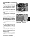
4. Loosen cap screw securing the idler to the counter
shaft housing (Fig. 37). Pivot idler pulley counterclock-
wise away from the backside of belt to release belt ten-
sion (Fig. 39).
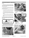
Note: The locking collar securing the left differential
axle to the countershaft housing is a eccentric flange
type.
5. Loosen the set screw on the locking collar. Unlock
collar by striking it with a punch in the clockwise direction
(Fig. 38).
6. Remove bearing housing for the left differential axle
(see Differential Axle Pulley and Bearing Removal).
IMPORTANT: For the remainder of this procedure,
support the axle in its original position to prevent
possible damage to the differential axle bearing and
differential housing bearing.
7. Remove bearing housing for the right differential
axle (see Differential Axle Pulley and Bearing Removal).
8. Remove differential boot (43) and rear box cover
(38) from the countershaft housing (1) and differential
axle (Fig. 33).
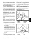
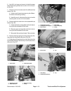
9. Remove jam nuts, lock washers, and cable clip from
the studs of screw plate. Slide locking collar and flan-
gettes with the bearing off the differential axle. This step
allows the differential assembly to be positioned for
clearing the frame (Fig. 40).
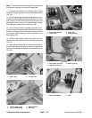
10. Pull differential assembly out and up from the coun-
tershaft housing.
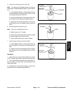
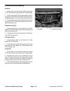
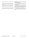
11. Remove lock nuts and flat washers from the differ-
ential assembly and pulley. Slide pulley clear of threads
and differential axle (Fig. 42).
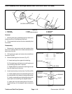
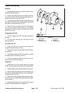
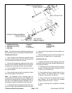
1. Cap screw & lock washer
2. Differential axle
3. Jam nut & lock washer
4. Flangettes
5. Locking collar
6. Screw plate stud
Figure 40
2
5
4
1
6
3
1. Idler pulley 2. Countershaft housing
Figure 41
1
2
1. Lock nut
2. Flat washer
3. Differential assembly
4. Differential pulley
Figure 42
4
2
1
3
Traction and Reel
Drive System