


Greensmaster 1000/1600Traction and Reel Drive Systems Page 4 – 14
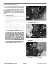
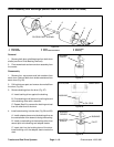
Differential Axle Pulley and Bearing
Removal
1. Remove drum drive belt from the drum drive assem-
bly (see Drum Drive Belt Replacement Removal).
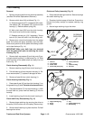
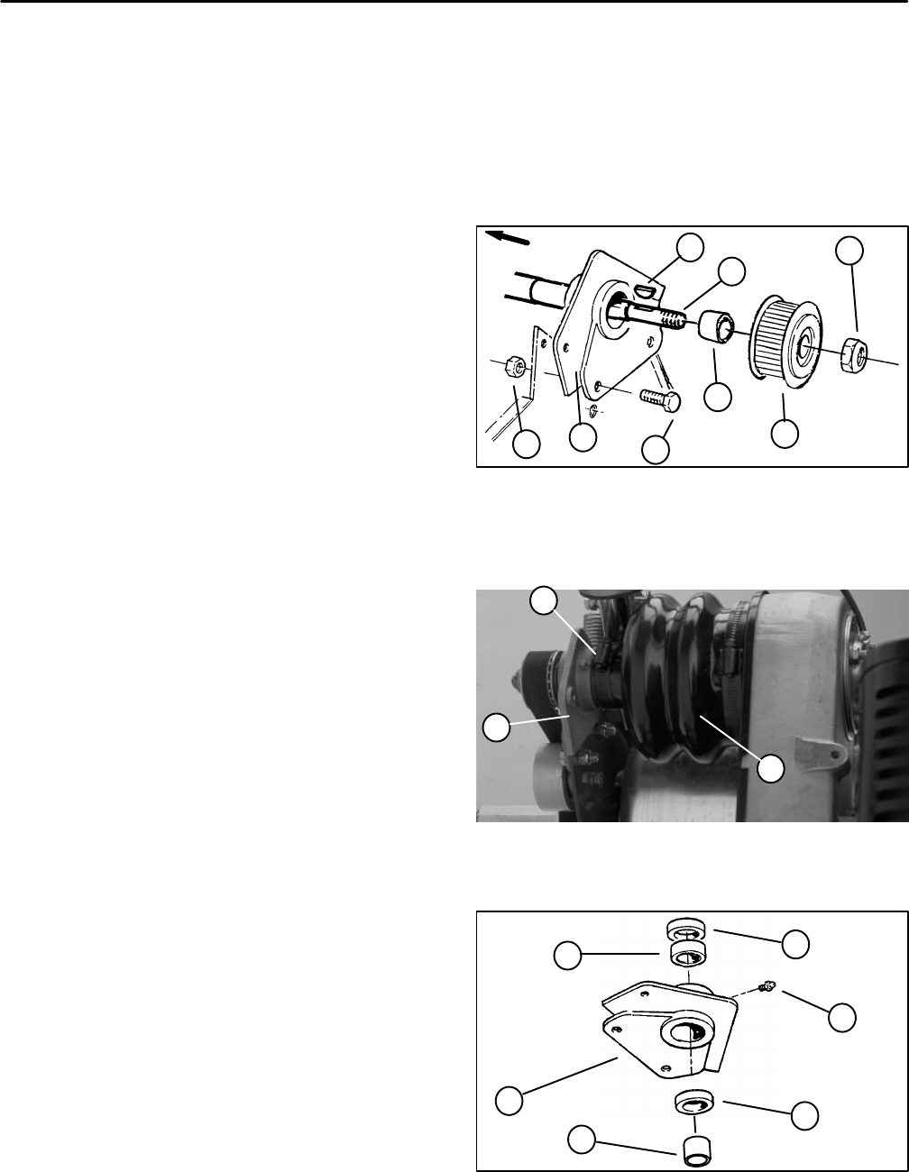
2. Remove nut from the differential axle. Remove
pulley and woodruff key from the axle (Fig. 19).
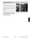
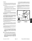
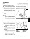
Note: On the housing (RH), the hose clamp must be
loosened and the differential boot must be removed
from the housing before the housing can be removed
from the frame and differential axle (Fig. 20).
3. Remove cap screw and lock nut from the housing
and frame. Slide housing off of the differential axle (Fig.
19).
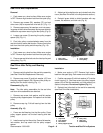
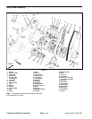
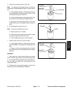
Disassembly (Fig. 21)
1. Remove spacer from housing and seal by. Replace
if worn or damaged.
2. Remove both seals from the housing. Discard both
seals and replace with new ones.
3. Pull bearing from housing and discard.
Assembly (Fig. 21)
1. Press seal with the flat side out into the housing side
opposite the grease fitting.
2. Press bearing into housing.
3. Press a second seal with the flat side out into the
grease fitting side of the housing
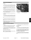
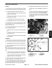
Installation (Fig. 19)
1. Park mower on a level surface. Make sure engine
is OFF. Remove high tension lead from the spark plug.
2. Slide housing over the differential axle with the
grease fitting towards the inboard side of the mower.
3. Secure housing to the frame with both cap screws
and lock nuts.
4. On the housing (RH), attach the differential boot to
the housing. Secure the hose clamp to the boot and
housing (Fig. 20).
5. Slide spacer onto differential axle. Press spacer into
seal until it contacts the inner race of the bearing.
6. Tap woodruff key into the key way of the differential
axle. Apply never seize the axle in the area of the keys.
7. Slide pulley onto the differential axle while aligning
pulley keyway with the woodruff key. Secure pulley to
the axle with the nut.
8. Replace drum drive belt to the drum drive assembly
and adjust belt tension (see Drum Drive Belt Replace-
ment Installation).
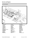
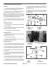
1. Nut
2. Differential axle
3. Pulley
4. Woodruff key
5. Cap screw
6. Lock nut
7. Housing
8. Spacer
Figure 19
6
5
8
3
1
4
2
7
INBOARD
SIDE
1. Hose clamp
2. Housing (RH)
3. Differential boot
Figure 20
1
2
3
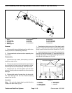
1. Spacer
2. Seal
3. Housing
4. Bearing
5. Grease fitting
Figure 21
2
4
2
1
3
5