


Greensmaster 1000/1600 Page 7 – 19 Cutting Unit
Installation
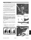
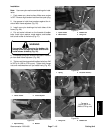
1. Make sure engine is OFF. Remove high tension
lead from the spark plug. Place mower on a flat level sur-
face or on a stable work bench.
IMPORTANT: Make sure the correct bearing hous-
ing is used when installing bearings. The grease fit-
ting hole should face forward when the housing is
placed in the frame.
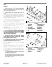
2. Reassemble bearing housing (LH) components
(Fig. 37).
A. Place small seal into the bearing housing with
the flat side out.
B. Press new bearing into the bearing housing with
a bearing driver.
C. Place large seal on the bearing housing with the
flat side out. Press seal in with a seal driver.
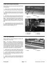
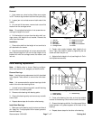
3. Reassemble bearing housing (RH) components
(Fig. 36).
A. Bearing housing (RH) should be marked from
disassembly.
B. Place small seal into the bearing housing with
the flat side out.
C. Place new wave washer into housing. Press
new bearing into the bearing housing with a bearing
driver.
D. Install and seat retaining ring into the groove of
the housing.
E. Place large seal on the bearing housing with the
flat side out. Press seal in with a seal driver.
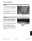
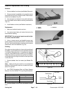
4. Position reel in frame to accept bearing housings.
The reel shaft end with internal threads should be on the
right side of the frame.
Note: The two bearing housings are similar in appear-
ance but can not be interchanged. The bearing housing
(RH) was marked during disassembly.
5. Attach bearing housing (RH) through the frame onto
the reel shaft (Fig. 36).
A. Push housing onto reel shaft. If necessary, tap
into position with a soft hammer.
B. Make sure grease fitting hole is position to the
front of the mower.
C. Attach the groomer arm cover to the bearing
housing and frame with the two flat head screws,
cover standoffs, and lock nuts. Do not tighten down
fasteners.
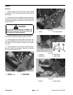
6. Attach bearing housing (LH) through the frame onto
the reel shaft (Fig. 37).
A. Push housing onto reel shaft. If necessary, tap
into position with a soft hammer.
B. Make sure grease fitting hole is position to the
front of the mower.
C. Align housing holes to frame holes with both cap
screws and lock nuts. Fasteners should be only fin-
ger tight.
7. While tightening the bearing lock nut (Fig. 37) to the
reel shaft, tighten pulley and drive assembly (Fig. 36) to
the reel shaft at the same time. Torque assembly and nut
to 50 ft–lb (6.9 kg–m).
8. Tighten flat head screws and nuts securing the
bearing housing (RH) to the frame (Fig. 36).
9. Remove both cap screws and lock nuts holding the
bearing housing (LH) to the frame. Position bearing cov-
er to housing and secure to frame with both cap screws
and lock nuts (Fig. 37).
10. Reinstall reel drive belt to the pulley and drive as-
sembly (see Service and Repair section of Chapter 4
Traction and Reel Drive Systems).
11. Reinstall reel drive cover with four lock washers and
cap screws to the mower. Tighten cap screws (Fig. 36).
12. Reinstall grease fittings to both bearing housings.
Lubricate both housings with No. 2 multipurpose lithium
base grease (Fig. 37 and 36).
13. Reinstall bedbar to the mower (see Bedbar Remov-
al).
14. Complete mower set–up and adjustment sequence
(see Adjustments section).
Cutting Unit