


Greensmaster 1000/1600 Traction and Reel Drive SystemsPage 4 – 29
Differential Belt Replacement – Models 04051, 04052, and 04060
1. Park mower on a level surface. Make sure engine
is OFF. Remove high tension lead from the spark plug.
2. Remove capscrews and lock washers securing the
drum belt and reel drive covers to the right side plate.
Remove belt covers.
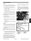
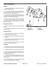
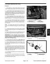
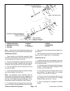
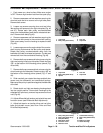
3. Loosen cap screws securing drum and reel drive
idler pulleys and spacers to the right side plate (Fig. 46
and 47). Rotate each idler pulley counterclockwise
away from the backside of each belt to release belt ten-
sion. Remove both belts(Fig.48).
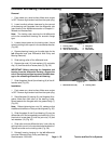
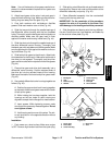
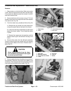
4. Remove capscrews and lock washers securing the
front and rear box covers to the counter shaft housing.
Slide covers away from the housing to expose the belt
(Fig. 48).
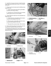
5. Loosen cap screw on the engine side of the counter-
shaft housing that secures the idler pulley and spacer.
Rotate idler pulley counterclockwise away from the
backside of the belt to release belt tension. Cut belt and
remove belt from the countershaft housing (Fig.48).
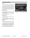
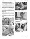
6. Remove both cap screws and locknuts securing the
right rear bearing housing to side plate. Rotate housing
180_ so the bottom of the housing points upward (Fig.
46 and 48).
7. Remove both cap screws and lock nuts securing the
clutch housing to the side plate. Rotate housing 180_ so
the bottom of the housing points upward (Fig. 47 and
48).
8. Slide new belt over rotated housings and both box
covers onto the differential and countershaft pulleys.
Make sure idler pulley is positioned against the backside
of the belt.
9. Rotate clutch and right rear bearing housings back
into the upright position. Secure both housings to the
sideplate with previously removed cap screws and lock
nuts (Fig.48).
10. Adjust differential belt tension and reinstall rear and
front box covers (see Differential Belt Adjustment).
11. Adjust belt tension on traction drive and reel drive
belts and reinstall covers (see Drum Drive and Reel
Drive Belt Adjustments).
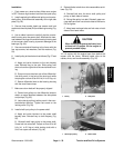
1. Cap screw
2. Idler pulley (Drum drive)
3. Lock nut
4. Cap screw
Figure 46
3
1
2
4
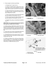
1. Cap screw
2. Idler pulley (Reel drive)
3. Spacer
4. Lock nut
5. Cap screw
Figure 47
1
2
3
4
5
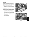
1. Idler pulley (Drum drive)
2. Idler pulley (Reel drive)
3. Belt (Reel Drive)
4. Belt (Drum drive)
5. Front box cover
6. Rear box cover
7. Countershaft housing
8. Idler pulley (Differential)
9. Belt
10. Bearing housing
11. Clutch housing
Figure 48
6
4
1
8
9
3
2
5
10
11
7
Traction and Reel
Drive System