


Greensmaster 1000Grooming Reel Kit Page 8 – 10
Disassembly
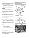
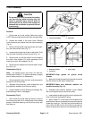
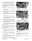
Inspect grooming reel blades frequently for damage and
wear. Straighten bent blades with a pliers. Either replace
worn blades or reverse the grooming reel shaft to put the
sharpest blade edge forward (Fig. 8).
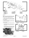
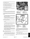
1. Remove one lock nut from either end of the shaft
(Fig. 9).
2. Remove spacers and blades as necessary.
Reassembly
1. Start placing two spacers against the lock nut. Then,
place blade against spacers (Fig. 9).
2. Rotate location mark on each blade one flat of the
shaft, either in a clockwise or counterclockwise direc-
tion. The direction of rotation must remain constant on
the shaft (Fig. 8).
3. Make sure there are two spacers between each
blade. Blades and spacers should be centered on the
shaft (Fig. 9).
4. Screw lock nut on the shaft and torque both lock
nuts from 200 to 250 ft–lb (27.7 to 34.6 kg–m) so
spacers are not free to rotate.
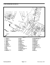
Installation
Note: The driven pulley (42) has left handed threads.
1. Park mower on a level surface. Make sure engine
is OFF. Remove high tension lead from the spark plug.
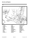
2. Place grooming reel shaft (53) into the belt drive
housing (46). Screw driven pulley (41) on the shaft. Do
not tighten (Fig. 5).
3. From the right side of the mower, install the following
(Fig. 5):
A. Install bearing housing (4) onto the other end of
the shaft (53) and side plate (8).
B. Secure the bearing housing to the side plate with
three flat head socket screws (50) and lock nuts (3).
C. Secure lock nut (1) to the shaft.
4. While holding the lock nut (1), tighten driven pulley
(42) to the shaft (53) (Fig. 5).
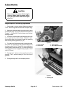
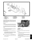
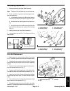
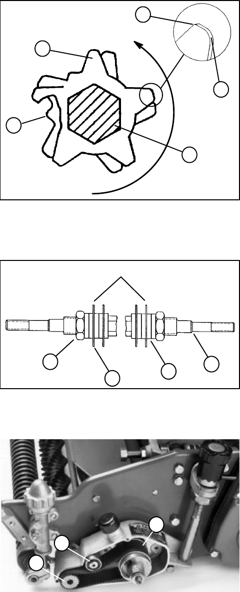
5. Reinstall drive belt onto the driven pulley. Adjust
drive belt tension (see Drive Belt Tension in Adjustments
section) and torque socket head cap screw from 7 to 10
ft–lb (1.0 to 1.4 kg–m) (Fig. 10).
6. Secure belt cover to housing with three socket head
cap screws and washers (Fig. 7). Reinstall poly washer
and clutch knob to clutch assembly. Tighten both set
screws into the clutch knob (Fig. 6).
1. Dull rounded edge
2. Sharp pointed edge
3. Grooming blade
4. Location mark
5. Shaft
Figure 8
ROTATION
2
1
4
3
5
1. Lock nut
2. Shaft
3. Spacer
4. Blade
Figure 9
1
3
4
2
CENTER BLADES
1. Drive belt
2. Driven pulley
3. Socket head cap screw
Figure 10
3
1
2