


Greensmaster 1000/1600
Page 6 – 11
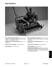
Wheels and Accessories
Wheels
Removal
1. Park mower on a level surface. Make sure the en-
gine is OFF.
2. Push kickstand down with one foot while pulling up
on the handle. This will support the mower on the kick
stand.
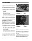
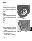
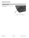
3. Pivot wheel locking clip away from the center of the
wheel. Slide wheel off the wheel shaft.
Note: The right hand wheel shaft has left hand
threads.
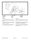
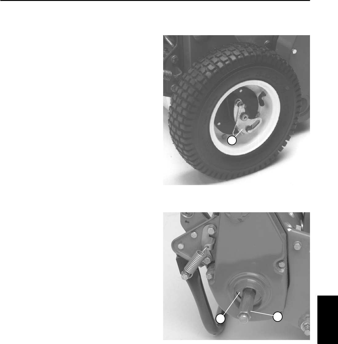
4. If necessary, remove wheel shaft from the drive
pulley.
Installation
1. Make sure mower is parked on a level surface and
the engine is OFF.
2. Push kickstand down with one foot while pulling up
on the handle. This will support the mower on the kick
stand.
Note: The right hand wheel shaft has left hand
threads.
3. If the wheel shafts were removed from the drive pul-
leys,
A. Apply Loctite 242 or equivalent to the threads of
the wheel shafts.
IMPORTANT:The right hand wheel shaft has left
hand threads.
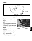
Note: The drum shafts inboard of the side plates have
flats that can be used while torquing the wheel shafts.
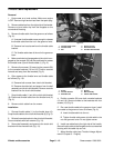
B. Install right hand wheel shaft into the drive pulley
on the right side of the mower. Install the remaining
shaft. Torque both shafts from 65 to 75 ft–lb (9.0 to
10.3 kg–m).
4. Apply anti–seize lubricant to the exposed end of the
wheel shaft.
5. Slide wheel onto the wheel shaft.
A. Pivot wheel locking clip away from the center of
the wheel.
B. Allow wheel to slide onto the shaft until the lock-
ing clip is secured into the groove on the wheel
shaft.
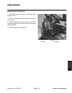
1. Locking clip
Figure 11
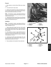
1
1. Wheel shaft 2. Drive pulley
Figure 12
1
2
Wheels and
Accessories