


Greensmaster 1000Grooming Reel Kit Page 8 – 12
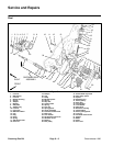
Clutch Assembly
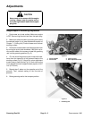
CAUTION
Do not use your hand to prevent the cutting
reel from turning while servicing; this can
result in personal injury. Insert a block of
hard wood into the front of the cutting unit
between the reel blades to prevent the reel
from turning.
Removal
1. Park mower on a level surface. Make sure engine
is OFF. Remove high tension lead from the spark plug.
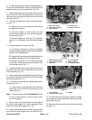
2. Loosen set screws in the clutch knob. Remove
clutch knob and poly washer from the clutch assembly
(Fig. 6).
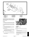
3. Remove three socket head cap screws and wash-
ers, then remove belt cover (Fig. 7).
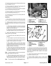
4. Loosen socket head cap screw on idler block. Pivot
idler to loosen drive belt and remove belt (Fig. 14).
5. Remove lock nut and flat washer from the shaft of
the clutch drive adapter. Pull clutch assembly off the
shaft of the clutch drive adapter (Fig. 6).
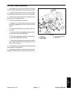
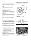
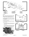
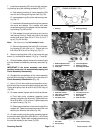
6. Remove clutch adapter from the reel shaft if neces-
sary (Fig. 15).
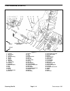
Disassembly (Fig. 6)
Note: The special screw and clutch pin were as-
sembled with Loctite 271. It might be necessary to apply
heat to these parts prior to disassembly.
1. Remove special screw, clutch pin, and compression
spring from the driver pulley.
2. Separate flange bushing, clutch release disc, and
both belleville washers from the driver pulley.
3. Inspect needle and roller bearings for damage. Re-
place bearings if worn or damaged.
Reassembly (Fig. 6)
1. Pack needle and roller bearings and the inside of
the driver pulley with No. 2 multipurpose lithium based
grease. Press both bearings into the driver pulley with
seal side out.
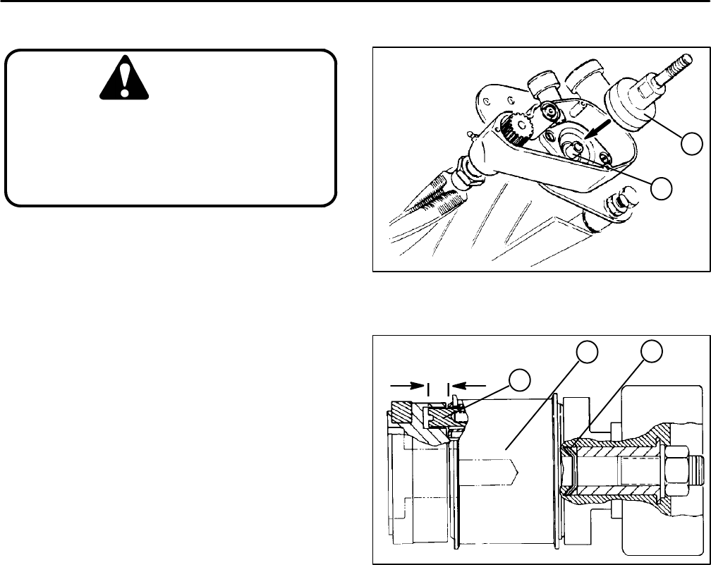
1. Clutch drive adapter 2. Reel shaft
Figure 15
1
2
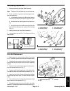
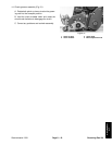
1. Belleville washers
2. Clutch pin
3. Driver pulley
Figure 16
0.240 to 0.260 inch
(6.10 to 6.60 mm)
1
2
3
IMPORTANT: Keep grease off special screw
threads.
2. Apply a thick coat of grease to the special screw and
the cam surface of the clutch release disc.
IMPORTANT: Make sure belleville washers are
installed correctly (Fig. 16).
3. Assemble both belleville washers, clutch release
disc, and flange bushing to the driver pulley.
4. Insert special screw through the clutch release disk,
driver pulley and compression spring.
5. Apply Loctite 271 or equivalent to the threads of the
special screw. Secure compression spring to the special
screw with clutch pin. The clutch pin should extend out
from 0.240 to 0.260 inch (6.10 to 6.60 mm) the face of
the driver pulley when the pin is fully extended (Fig. 16).