


Greensmaster 1000/1600Page 7 – 20Cutting Unit
Preparing a Reel for Grinding
Note: Check to make sure the reel bearings are in
good condition and properly adjusted before grinding a
reel.
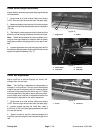
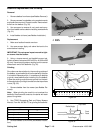
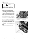
1. Remove bedbar assembly (see Bedbar Removal).
2. Raise grooming reel, if installed, by rotating both
quick–up levers so they face the rear of the mower.
Note: Some older grinding machines may require that
the cutting reel be removed.
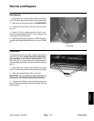
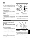
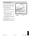
3. Remove roller and both height–of–cut arms (see
Roller Removal).
Note: The cutting unit must be aligned so the grinding
wheel will travel parallel to the reel shaft. This will result
in the the reel being ground to the desired cylinder
shape.
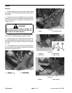
Note: When grinding, be careful to not overheat the
reel blades. Remove small amounts of material with
each pass of the grinder.
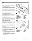
4. After completing grinding process:
A. Install height–of–cut arms and roller (see Roller
Installation).
B. Install bedbar assembly (see Bedbar Installa-
tion).
C. Complete mower set–up and adjustment se-
quence (see Adjustments section).
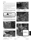
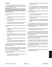
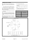
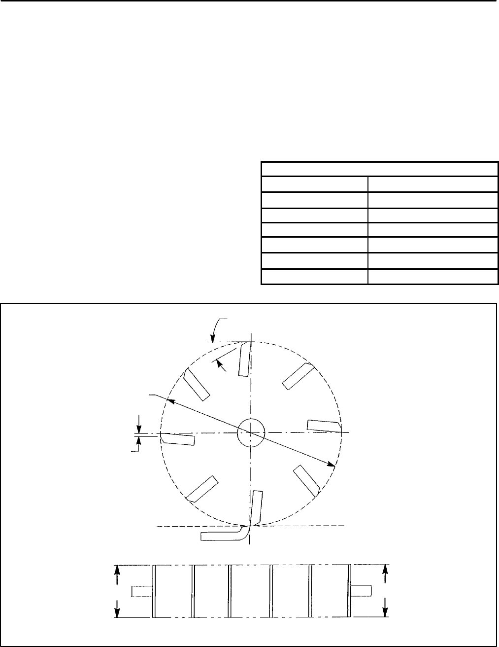
Reel Grinding Specifications
Nominal Reel Diameter
5 in (126 mm)
Service Limit Reel Diameter
4.5 in (114 mm)
Blade Relief Angle
30_
Relief Angle Range
20_ to 40_
Blade Land Width
0.040 in (1.0 mm)
Land Width Range
0.030 to 0.060 in (0.7 to 1.5 mm)
Max. Reel Taper
0.040 in (1.0 mm)
REEL DIAMETER TAPER = D
1
– D
2
D
1
D
2
BLADE RELIEF ANGLE
REEL DIAMETER
BLADE
LAND
WIDTH
Figure 38