


Greensmaster 1000Grooming Reel Kit Page 8 – 18
7. Install frame assembly (RH) onto the right reel bear-
ing housing using the following procedure (Fig. 27):
A. Slide bearing housing of frame assembly (RH)
over the end of the grooming reel shaft (Fig. 28)
B. Insert adapter ring (9) into the reel bearing hous-
ing (Fig 17).
C. Insert both flat head screws through the groomer
arm cover and adapter. Put a spacer over each
screw before placing the adapter into the reel bear-
ing housing (Fig. 28 and 29).
D. Slide adapter through the bearing and into the
reel bearing housing. Install lock nuts on flat head
screws and torque from 23 to 27 ft–lb (3.2 to 3.7
kg–m) (Fig. 28 and 29).
Note: The lock nut (1) has left handed threads.
E. Secure the grooming reel shaft (53) to the bear-
ing housing (4) with lock nut (1). Torque lock nut
from 29 to 35 ft–lb (4.0 to 4.8 kg–m) (Fig 17).
8. Secure mounting block (22) to the frame with cap
screw (11) and belleville washer (12) (Fig. 17 and 29).
9. Reinstall bedbar adjuster frame to the mower frame
with cap screws and washers previously removed (Fig.
28).
IMPORTANT: If the clutch assembly was disas-
sembled, make sure it is reassembled properly (see
Clutch Assembly Reassembly).
10. Complete the reinstallation of the clutch assembly
and belt drive housing by following the instructions in
Clutch Assembly Reinstallation (Fig. 30).
11. Use a 1/2–inch drive ratchet and extension to rein-
stall drive pulley and reel drive belt to cutting reel shaft.
Torque drive pulley from 40 to 60 ft–lb (5.5 to 8.3 kg–m)
(Fig. 29).
12. On newer models, tighten reel drive belt as follows:
A. Pivot idler pulley clockwise (opposite arrow
direction) to tighten reel drive belt. Tighten belt from
20 to 25 lb (89 to 111 N) of force. Tighten cap screw
on clutch housing. (Fig. 21).
B. Raise grass shield to 4 inches from the top of the
support rod. Tighten both cap screws and lock nuts
securing the shield to the frame (Fig. 20).
13. On older model, pivot idler pulley assembly against
the reel drive belt. Apply 20 to 25 lb (89 to 111 N) of force
to the idler pulley. Tighten both carriage bolts securing
the reel idler bracket to the frame (Fig. 29).
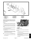
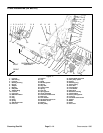
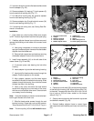
1. Bearing 2. Bearing housing
Figure 27
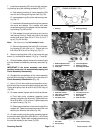
FRAME ASSEMBLY (RH)
1
2
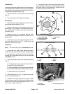
1. Bedbar adjuster frame
2. Cap screw and washer
3. Side plate
4. Groomer adjuster
5. Bearing housing
6. Grooming reel shaft
Figure 28
2
4
6
1
3
5
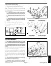
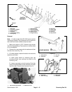
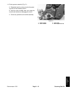
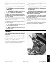
1. Reel idler bracket
2. Idler pulley assembly
3. Reel drive belt
4. Flat head screw
5. Groomer arm cover
6. Mounting block
7. Drive pulley
8. Reel drive belt
Figure 29
1
2
3
4
5
6
8
7
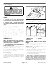
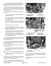
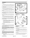
1. Drive belt
2. Driven pulley
3. Clutch drive housing
Figure 30
1
2
3