


Greensmaster 1000Grooming Reel Kit Page 8 – 16
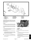
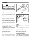
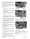
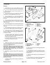
4. On older models, loosen both carriage bolts secur-
ing the reel idler bracket to the frame. Pivot idler pulley
assembly away from the reel drive belt. (Fig. 22).
5. Secure cutting reel from turning with a block of hard
wood. Use a 1/2–inch drive ratchet with an extension to
remove the drive pulley and drive belt from the cutting
reel shaft (Fig. 22).
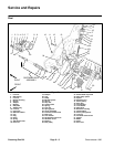
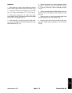
6. From the right side of the mower, remove the follow-
ing (Fig. 17):
A. Remove lock nut (1) securing the shaft (53) to
the bearing housing (4).
B. Use allen wrench to remove both flat head
screws. Remove groomer arm cover from reel bear-
ing housing (Fig. 22).
C. Remove adapter (6), bearing (7) if necessary,
spacers (5), and adapter ring (9) from the side plate
(8).
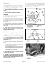
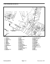
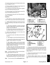
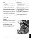
7. On both sides of the mower (Fig. 23),
A. Use spring compressor or clamp to compress
springs in bedbar adjuster frames to free the bedbar
adjuster from the bedbar ear.
B. Remove both cap screws and washers securing
the bedbar adjuster frame to the mower frame.
C. Remove cap screw (11) and belleville washer
(12) (inside of frame) securing mounting block (22)
to the mower frame (Fig. 17).
8. Loosen both set screws on the clutch knob. Remove
the clutch knob and the poly washer behind it from the
clutch assembly (Fig. 18).
9. Remove the three socket head cap screws (33) and
lock washers (32). Remove belt cover (31) from the belt
drive housing (46) (Fig. 17).
10. In the belt drive housing (46), disassemble the fol-
lowing parts (Fig. 17):
A. Loosen socket head cap screw (37) and idler
pulley (36), then remove drive belt (42) from the
driven pulley (41).
Note: The driven pulley (42) has left handed threads.
B. Use an allen wrench to remove driven pulley
from the shaft (53).
11. Remove lock nut and flat washer from the shaft of
the clutch drive adapter. Pull clutch assembly off the
shaft of the clutch drive adapter (Fig. 18).
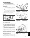
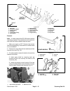
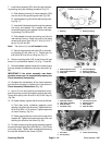
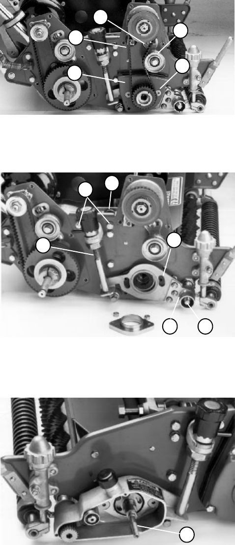
12. Secure cutting reel from turning with a block of hard
wood. Remove clutch adapter from reel shaft (Fig. 24).
1. Reel idler bracket
2. Idler pulley assembly
3. Reel drive belt
4. Flat head screw
5. Groomer arm cover
Figure 22
1
2
3
OLDER MODELS
4
5
1. Bedbar adjuster frame
2. Cap screw and washer
3. Side plate
4. Groomer adjuster
5. Bearing housing
6. Grooming reel shaft
Figure 23
2
4
6
1
3
5
1. Clutch adapter
2. Flat head socket screw
3. Adapter
Figure 24
1
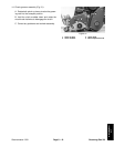
13. Pull side plate with the groomer adjuster and bear-
ing housing from the grooming reel shaft and reel bear-
ing housing (Fig. 23).
14. Remove grooming reel from the belt drive housing
(46) (Fig. 17).