


Greensmaster 1000 Grooming Reel KitPage 8 – 17
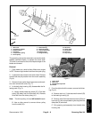
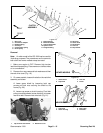
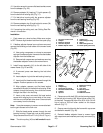
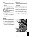
15. Use allen wrench to remove flat head socket screws
from the adapter (Fig. 25).
16. Remove adapter (6), bearing (7), both spacers (5)
from the belt drive housing (46) (Fig. 17).
17. Pull belt drive housing with the groomer adjuster
from the reel bearing housing (Fig. 25).
18. Remove adapter ring (9) and both slot covers (54)
from the reel bearing housing (Fig. 17).
19. If removing the cutting reel, see Cutting Reel Re-
moval in this section..
Installation
1. Park mower on a level surface. Make sure engine
is OFF. Remove high tension lead from the spark plug.
2. If bedbar adjuster frames have not been removed,
remove the following on both sides of the mower frame
(Fig. 25):
A. Use spring compressor or clamp to compress
springs in bedbar adjuster frames to free the bedbar
adjuster from the bedbar ear.
B. Remove both cap screws and washers securing
the bedbar adjuster frame to the mower frame.
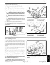
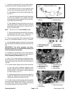
3. Install frame assembly (LH) to the left side of the
mower frame (Fig. 25 and 26).
A. If removed, press new bearing into belt drive
housing.
B. Insert adapter ring into the reel bearing housing.
C. Insert both flat head socket screws through the
adapter. Position spacers on the screws.
D. Align adapter, spacers, and flat head socket
screws with the slots in the belt drive housing. Slide
adapter through the bearing, then slide the screws
through the slots in the housing.
E. Insert a slot cover onto each flat head socket
screw while aligning the curved side of the cover
with the curve of the belt drive cover. Covers should
curve away from the housing.
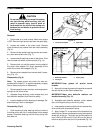
Note: It may be necessary to move or remove the bed-
bar tho gain access to the lock nuts.
F. Slide flat head socket screws through the reel
bearing housing. Screw lock nuts on both screws.
Torque screws from 23 to 27 ft–lb (3.2 to 3.7 kg–m).
Note: The driven pulley (42) has left handed threads.
1. Flat head socket screw
2. Adapter
3. Belt drive housing
4. Groomer adjuster
5. Bedbar adjuster frame
6. Adapter ring
7. Reel bearing housing
8. Spacer
9. Reel bearing lock nut
10. Driven pulley (removed)
Figure 25
7
8
2
6
1
10
2
1
9
4
3
5
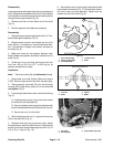
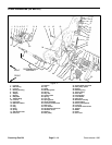
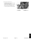
1. Bearing
2. Adapter ring
3. Reel bearing housing
4. Flat head socket screws
5. Adapter
6. Spacers
7. Belt drive housing
8. Slot cover
9. Lock nuts
10. Mounting block
11. Cap screw
12. Belleville washer
Figure 26
8
1
5
11
12
3
2
10
1
6
4
7
FRAME ASSEMBLY (LH)
9
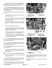
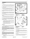
4. Place one end of shaft (53) into the bearing support
of the belt drive housing (46). Mount driven pulley (41)
to the shaft. Torque pulley from 29 to 35 ft–lb (4.0 to 4.8
kg–m) using a 3/8–inch allen socket on the torque
wrench (Fig. 17).
5. Secure mounting block to the frame with cap screw
and belleville washer (Fig. 26).
6. Reinstall bedbar adjuster frame to mower frame
with cap screws and washers previously removed (Fig.
25).
Grooming Reel
Kit