


Greensmaster 1000/1600
Page 6 – 8
Wheels and Accessories
Clutch Cable Replacement
Removal
1. Park mower on a level surface. Make sure engine
is OFF. Remove high tension lead from the spark plug.
2. Disengage clutch to release tension on the clutch
cable. Remove cable ties from the right side of the han-
dle.
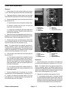
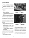
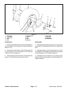
3. Remove clutch cable from the bellcrank assembly
as follows (Fig. 7):
A. Open bellcrank cover to access the clutch lever
and bracket.
B. Remove shoulder bolt and lock nut securing the
cable eyelet to the clutch lever.
C. Loosen rear nut attaching the clutch cable to the
clutch bracket. Remove clutch cable from the clutch
bracket.
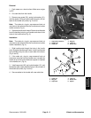
4. Make sure brake is disengaged and the clutch is en-
gaged so the console (29) can be positioned to access
the clutch lever (25) and clutch cable (12) (Fig. 2).
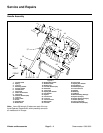
5. Remove four screws (13) securing the console (29)
to the console brackets (10 and 19). Position console
forward and away from the brackets (Fig. 2).
Note: On models without the operator presence kit,
the bail assembly is not installed on the handle assem-
bly. The shoulder bolt and spacer are substituted by an
additional screw on both sides of the handle assembly
(Fig. 2 and 8).
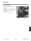
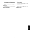
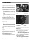
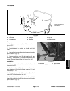
6. Gain access to the clutch lever and clutch cable as
follows (Fig. 8):
A. If the operator presence kit is installed, remove
both screws from clutch skid bracket. Remove
shoulder bolt and spacer from the bail assembly and
clutch skid bracket. Remove console bracket from
the clutch skid bracket.
B. If the operator presence kit is not installed, re-
move three screws and console bracket from the
clutch skid bracket.
7. Remove shoulder bolt (14) and lock nut (11) from
the clutch lever (25) and clutch cable (12) eyelet (Fig. 2).
8. Loosen nut securing the clutch cable (12) to the
clutch bracket (27). Remove cable from the clutch
bracket (Fig. 2).
9. Remove clutch cable from the mower.
1. Clutch lever
2. Clutch bracket
3. Shoulder bolt & lock nut
4. Cable eyelet
5. Rear nut
6. Clutch cable
Figure 7
3
4
5
2
1
6
1. Screw
2. Console bracket
3. Shoulder bolt
4. Spacer
5. Bail assembly
6. Clutch skid bracket
Figure 8
1
4
5
2
3
6
Installation
1. Secure clutch cable (12) eyelet to the clutch lever
(25) with the shoulder bolt (14) and lock nut (11) (Fig. 2).
Note: On models without the operator presence kit,
the bail assembly is not installed on the handle assem-
bly. The shoulder bolt and spacer are substituted by an
additional screw on both sides of the handle assembly
(Fig. 2 and 8).
2. If the operator presence kit is installed, reinstall con-
sole bracket to the clutch skid bracket. Secure brackets
with both screws. Secure bail assembly and spacer to
the clutch skid bracket with the shoulder bolt (Fig. 8).