


Greensmaster 1000/1600Traction and Reel Drive Systems Page 4 – 10
Clutch Bearing
Removal
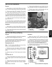
1. Remove reel drive belt from the reel drive assembly
(see Reel Drive Belt Replacement Removal).
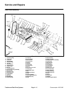
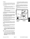
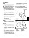
2. Remove clutch lever (24) as follows (Fig. 11):
A. Remove cap screw (27), lock washer (22), belle-
ville washer (26), and spacer (25) from the clutch
housing (1). Remove detent spring (20).
B. Work clutch boot (28) from the clutch housing.
Pull clutch lever from the clutch housing.
C. Replace actuator pin (19) if necessary. Torque
lock nut (21) from 45 to 60 in–lb (52 to 69 kg–cm).
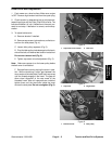
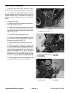
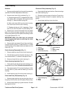
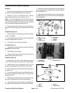
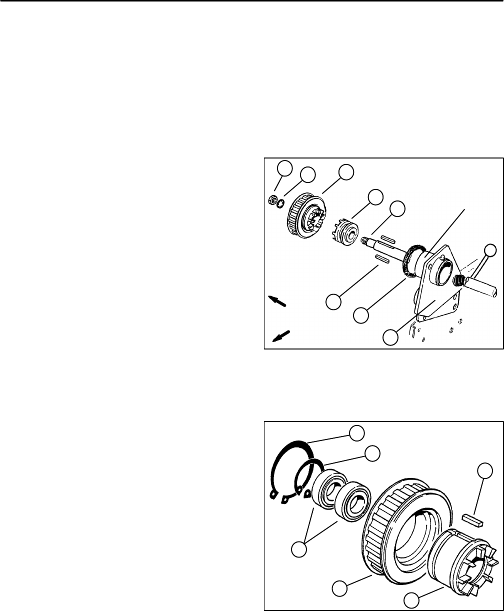
3. Remove jam nut and lock washer from the power
shaft. Pull clutch and pulley assembly from the shaft.
Slide clutch jaw driver off the power shaft being careful
not to lose the keys (Fig. 14).
IMPORTANT: Make sure both keys are removed
from the power shaft prior to removing the clutch
housing (Fig. 14).
4. Remove both cap screws (2) and lock nuts (3) se-
curing the clutch housing (1) to the frame (Fig. 11). Slide
clutch housing off the power shaft and away from the
frame (Fig. 14).
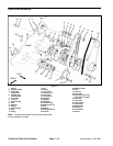
Clutch Housing Disassembly (Fig. 11)
1. Remove retaining ring (8) from clutch housing (1).
2. Pull ball bearing (4) from the clutch housing (1). Re-
move wave washer (7); replace if damaged or worn.
3. Remove oil seal (6) from clutch housing (1).
Clutch Housing Assembly (Fig. 11)
1. Press new oil seal (6) into the clutch housing (1) on
the grease fitting (5) side. Flat side of seal must be out.
2. Place wave washer (7) into clutch housing (1). With
the seal side out, press new ball bearing (4) into the
housing.
3. Install retaining ring (8) into the clutch housing (1).
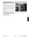
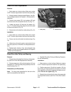
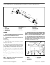
Clutch and Pulley Disassembly (Fig. 15)
1. Remove large retaining ring securing the driver to
the pulley. Pull the driver out of the pulley. Remove key.
2. Remove small retaining ring from the driver. Pull ball
bearings from driver.
Clutch and Pulley Assembly (Fig. 15)
1. Press new ball bearings into driver. Secure bearings
with small retaining ring.
2. Place key into the keyway of the driver. Press driver
through the pulley enough to expose retaining ring
groove.
3. Secure large retaining ring to the driver.
1. Jam nut
2. Lock washer
3. Power shaft
4. Clutch and pulley assy
5. Clutch jaw driver
6. Key
7. Clutch housing
8. Felt seal
Figure 14
1
2
4
5
6
8
7
OUTBOARD
SHOULDER
FRONT
RIGHT
3
1. Large retaining ring
2. Driver
3. Pulley
4. Key
5. Small retaining ring
6. Ball bearing
Figure 15
6
2
5
1
3
4