


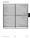

Greensmaster 1000/1600 Page 3 – 11 Engine
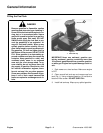
Removal
1. Make sure machine is parked on a level surface with
the engine OFF. Remove high tension lead from the
spark plug to prevent the engine from starting. Close
fuel shut–off valve.
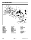
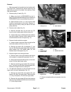
2. Remove pulley V–belts (Fig. 12).
A. Make sure clutch is DISENGAGED so the V–
belts (34) are slackened. Make sure service brake is
DISENGAGED so the input shaft pulley can turn.
B. Open bellcrank cover (1) on the counter shaft
housing to get access to the clutch. Remove V–
belts one at a time by sliding the belt off the idler
pulley (39) first.
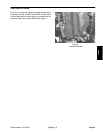
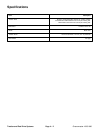
3. Remove clutch cable (Fig. 12).
A. Remove shoulder bolt (13) and lock nut (37)
from the clutch cable eyelet (49) and lever (9).
B. Loosen lower jam nut holding the clutch cable to
the clutch bracket. Remove clutch cable from the
clutch bracket and clear of engine (Fig. 13).
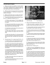
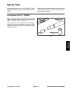
4. Remove throttle cable from engine.
A. Loosen screw on governor lever enough to slide
the throttle cable out of the nut (Fig. 14).
B. Remove cap screw (23), flat washers (7), and
lock nut (26) from the engine base (49) and throttle
cable bracket (24). Pull throttle cable (47) and
bracket clear of the engine (Fig. 12).
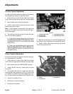
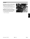
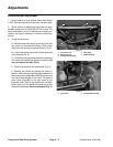
5. Remove engine from the engine base.
A. Scribe a mark on the engine base at the bottom
of the engine for reassembly purposes (Fig. 15).
B. Disconnect both black\white wires on the clutch
switch (16) from both brown wires.
C. Remove remaining cap screws (23), flat wash-
ers (7), and lock nuts (26) from the engine base (49).
Remove the engine from the cutting unit.
6. The bellcrank assembly can be removed from the
engine with minimum disassembly (Fig. 12).
A. Remove cap screw (36), lock washer (33), and
washer (35) from the engine shaft. Remove pulley
(11), key, and spacer (12) from the engine shaft.
B. Remove five cap screws (20) and lock washers
(33) securing the belt shield (29) and clutch bracket
(17) to the engine block.
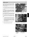
Figure 13
1. Lower jam nut 2. Clutch bracket
2
1
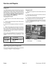
Figure 14
1. Screw
2. Governor lever
3. Throttle cable
4. Nut
5. Washer head screw
2
1
4
3
5
SLOW
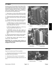
Figure 15
1. Engine block 2. Engine base
1
2
SCRIBE MARK
C. Remove complete bellcrank assembly from the
engine.
Engine