


Greensmaster 1000/1600Page 7 – 18Cutting Unit
Reel
Removal
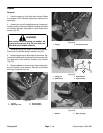
1. Make sure engine is OFF. Remove high tension
lead from the spark plug. Place mower on a flat level sur-
face or on a stable work bench.
2. Remove bedbar from the mower (see Bedbar Re-
moval).
3. If a grooming reel kit is installed, remove the cutting
reel using the procedures in Frame Assembles (RH and
LH) and Cutting Reel in the Service and Repairs section
of Chapter 8 – Grooming Reel Kit.
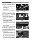
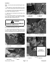
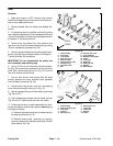
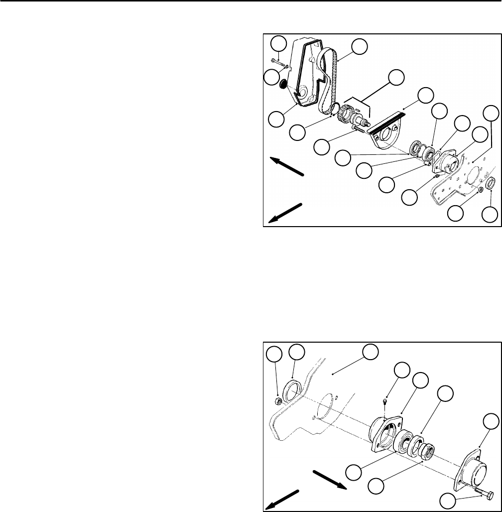
4. Remove four cap screws, four lock washers, and
reel drive cover from the mower. Mark bearing housing
(RH) for reassembly purposes (Fig. 36).
5. Remove reel drive belt from the pulley and drive as-
sembly (see Service and Repair section of Chapter 4 –
Traction and Reel Drive Systems.
IMPORTANT: Do not disassemble the pulley and
drive assembly and retaining ring.
6. Use a 1/2–inch drive in the pulley and drive assem-
bly (Fig. 36) to remove the assembly from the reel drive
shaft. Also, remove bearing lock nut (Fig. 37) from the
reel drive shaft at the same time.
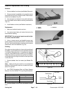
7. Use an allen wrench and remove both flat head
screws, groomer arm cover, and both cover standoffs
from the bearing housing (Fig. 36).
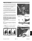
8. Remove both cap screws, lock nuts, and bearing
cover from the bearing housing (LH) (Fig. 37).
9. Remove grease fittings from both bearing housings
(Fig. 36 and 37).
10. Pull both bearing housings from the frame and reel
(Fig. 36 and 37). Remove the reel from the mower.
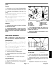
11. If bearings are worn or need replacement for main-
tenance purposes, remove bearings from both bearing
housings as follows:
A. Remove large seal, small seal, and bearing from
the bearing housing (Fig. 37).
B. Remove bearing seal, retaining ring, bearing,
and wave washer from the bearing housing. Discard
wave washer (Fig. 36).
1. Grease fitting
2. Cap screw
3. Lock washer
4. Reel drive cover
5. Reel drive belt
6. Pulley and drive assy
7. Retaining ring
8. Flat head screw
9. Nut
10. Groomer arm cover
11. Cover standoff
12. Bearing housing (RH)
13. Frame
14. Large seal
15. Small seal
16. Retaining ring
17. Bearing
18. Wave washer
Figure 36
15
14
16
11
8
6
10
17
18
12
13
3
4
2
5
RIGHT
FRONT
7
1
9
1. Grease fitting
2. Bearing housing (LH)
3. Cap screw
4. Lock nut
5. Bearing cover
6. Bearing lock nut
7. Large seal
8. Small seal
9. Bearing
10. Frame
Figure 37
RIGHT
FRONT
10
4
8
1
2
7
5
9
6
3