


Greensmaster 1000/1600 Traction and Reel Drive SystemsPage 4 – 11
Installation
1. Park mower on a level surface. Make sure engine
is OFF. Remove high tension lead from the spark plug.
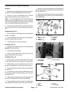
2. If the felt seal is damaged or worn, replace seal as
follows (Fig. 14):
A. Completely remove seal and adhesive from the
out board shoulder of the clutch housing.
B. Apply 3M adhesive EC–1099 or equivalent to
the outboard shoulder of the housing. Attach seal to
housing.
C. Fill clutch housing about half full with No. 2 multi-
purpose lithium base grease.
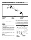
3. Slide clutch housing (1) onto the power shaft (9) with
oil seal (6) towards the shaft. Be careful not to damage
the seal (Fig. 11).
4. Place both cap screws (2) through the bearing
housing (1) and frame. Secure cap screws with both lock
nuts (3). Make sure clutch housing fits tightly
against the edge of the frame (Fig. 11).
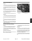
5. Tap both keys into the keyways of the power shaft.
Apply Never Seize to the area of the keys and bearing
journal of the clutch jaw driver (Fig. 14).
6. Place clutch jaw driver on the shaft with the jaws fac-
ing out. Align slots in the clutch jaw driver with the keys
and slide into position (Fig. 14).
7. Place clutch and pulley assembly on the power
shaft with the jaws facing the clutch jaw driver. Secure
assembly to the shaft with the lock washer and jam nut
(Fig. 14).
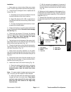
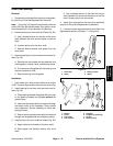
8. Place end of clutch lever (24) with actuator pin (19)
through the clutch housing (1). Seat clutch boot (28) in
the hole of the housing (Fig. 11).
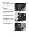
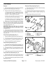
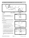
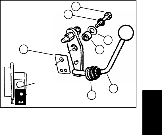
9. Install clutch lever to the clutch housing (Fig. 16).
A. Place lock washer, belleville washer, and spacer
on the cap screw. Make sure concave side of
belleville washer faces the clutch lever when
installed.
Note: On newer models, the detent spring is symmet-
rical. The spring can be installed in either direction.
B. Insert cap screw with the washers and spacer
through the hole in the clutch lever. Place detent
spring on cap screw with the two small holes
down and the hole closest to the edge away
from the lever.
C. With the actuator pin engaging in the groove of
the clutch jaw driver (slide driver all the way into the
housing), secure cap screw into the clutch housing
(Fig. 14).
10. Make sure clutch engages and disengages with no-
ticeable detent and without binding. It may be necessary
to rotate the clutch pulley assembly (12) to achieve en-
gagement (Fig. 11).
11. Reinstall reel drive belt to the reel drive assembly
and adjust belt (see Reel Drive Belt Replacement Instal-
lation).
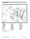
1. Lock washer
2. Belleville washer
3. Spacer
4. Cap screw
5. Clutch lever
6. Detent spring
7. Clutch boot
Figure 16
6
4
1
2
3
5
7
SPRING SHOULD BE
FLUSH TO HOUSING
SHOULDER
Traction and Reel
Drive System