


Greensmaster 1000/1600
Page 5 – 8
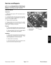
Electrical System
Component Testing
For accurate resistance and/or continuity checks, elec-
trically disconnect the component being tested from the
circuit (e.g. unplug the ON/OFF switch connector before
doing a continuity check). Individual components should
be electrically isolated (e.g. disconnect all leads or re-
move from circuit) from the circuit when tested.
CAUTION
When testing electrical components for
continuity with a multimeter (ohms set-
ting), make sure that power to the circuit
has been disconnected.
NOTE: See the Kawasaki FE161 & FE170 Service
Manual and Kawasaki FE120 Service Manual Sup-
plement for more component testing information.
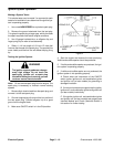
The ignition system produces a danger-
ously high voltage. Do not touch the
spark plug, ignition coil, igniter, or spark
plug lead while the engine is running;
you can receive a severe electrical
shock.
WARNING
Interlock Module and Clutch (Interlock) Switch – No Operator Presence Control
The interlock module prevents the engine from starting
unless the clutch switch is closed (clutch DISEN-
GAGED). After a safe start, the engine will continue to
run with the clutch switch open (clutch ENGAGED) or
closed.
If the engine will not start, perform the following tests to
determine if the interlock module or clutch switch is at
fault.
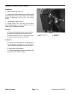
1. Check that there is a good ground between the in-
terlock module and the engine, Check all other electrical
connections and the interlock module for damage. Re-
place any damaged wiring or components.
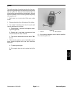
2. Check the adjustment and continuity of the clutch
switch.
A. Disconnect both black\white wires from both
brown wires connected to the interlock module.
B. Place traction clutch lever in the ENGAGED
position. The switch should be open.
C. Place traction clutch lever in the DISENGAGED
position. The switch should be closed.
D. Adjust interlock switch until it opens and closes
properly when the traction lever is in the ENGAGED
and DISENGAGED positions. See Interlock Switch
in the Adjustments section.
E. Reconnect both brown wires to both black\white
wires connected to the clutch switch.
3. Start the engine. If the engine does not start, check
the interlock module using the following steps.
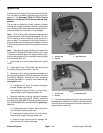
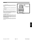
4. Disconnect red wire (male connector) where it con-
nects to the black wire leading to the ignition coil. On old-
er models, disconnect red wire (male connector) where
it connects to the black wires leading to the ignition coil
and igniter.
A. Start the engine. The engine should start.
B. Ground the red wire (male connector) to the en-
gine block and start the engine. The engine should
not start.
C. Reconnect the red wire to the black wire.
5. Disconnect both brown wires from both black\white
wires.
A. Start the engine. The engine should not start.
B. Jumper across the two brown wires and start the
engine. The engine should start.
C. Reconnect both black\white wires to both brown
wires.
6. Replace interlock module if it fails either off the tests
in step 4 or 5.