


Greensmaster 1000/1600Traction and Reel Drive Systems Page 4 – 34
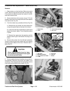
11. Secure engine to the frame as follows:
A. Reinstall both V–belts (Fig. 51).
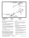
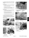
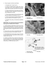
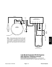
A. Position the engine base to obtain from 5.34 to
5.46 inches (13.6 to 13.9 cm) between the engine
output shaft and power shaft center lines (Fig. 65).
B. Align machined face of input power and shaft in-
put pulleys to within a maximum of 0.03 inch (0.76
mm) misalignment (Fig. 65).
C. Secure engine base to the front of the frame with
two cap screws and lock washers (Fig. 51).
D. Secure engine base to the back of the frame with
two cap screws and lock washers (Fig. 50).
E. Reinstall idler pulley to the bellcrank assembly
(Fig. 51).
IMPORTANT: Over tightening belts will overload the
bearings and increase wear on the belt.
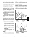
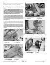
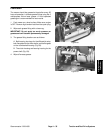
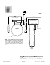
12. Adjust tensions of differential and both drum drive
belts from 20 to 25 lbs (89 to 111 N) of force. Use a scale
to pull on the idler pulley while securing the idler brack-
ets by tightening both carriage bolts and lock nuts (Fig.
66).
13. Secure box cover to the countershaft housing with
the three cap screws and lock washers (Fig. 50)
14. Reinstall both drum drive covers using a 7/16–inch
socket to tighten the four cap screws and lock washers
to each cover (Fig. 49).
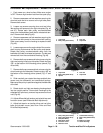
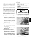
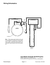
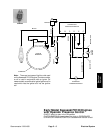
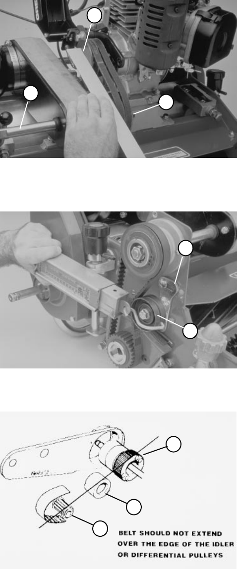
15. Start the unit and run for a minimum of one minute.
Shut the engine off. The inside edge of the differential
belt should not hang over either the idler pulley, counter-
shaft pulley, or differential pulley (Fig. 67).
1. Power shaft
2. Input power pulley
3. Shaft input pulley
Figure 65
1
1
3
1. Idler pulley 2. Idler pulley bracket
Figure 66
2
1
1. Differential pulley
2. Counter shaft pulley
3. Idler pulley
Figure 67
1
3
2