


Greensmaster 1000/1600
Page 5 – 13
Electrical System
Service and Repairs
NOTE: See the Kawasaki FE161 & FE170 Service
Manual and Kawasaki FE120 Service Manual Sup-
plement for more component repair information.
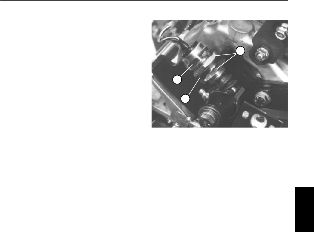
Interlock Switch
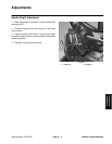
Adjustment
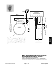
1. Make sure the engine is OFF and traction lever is
DISENGAGED.
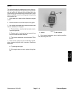
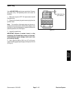
2. Loosen both switch mounting nuts and move switch
until the switch plunger is depressed 0.18 to 0.24 inch
(4.6 to 6.1 mm) (switch closed).
3. Tighten switch mounting nuts.
4. Engage traction lever and verify that the switch
plunger is depressed no more than 0.06inch (1.5 mm)
(switch open). Readjust as required.
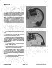
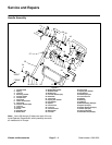
Removal
A. Disconnect black\white wires at the switch from
the brown wires leading from the Interlock module.
B. Remove adjusting nut from the plunger side of
the switch. Remove switch from bracket.
Installation
A. Place switch into bracket with one adjusting nut
and the plunger end facing the clutch lever. Thread
remaining adjustment nut onto the switch.
B. Adjust switch as necessary.
C. Connect black\white wires at the switch to the
brown wires from the interlock module.
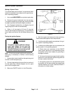
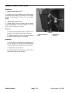
1. Interlock switch
2. Adjusting nut
3. Bracket
Figure 8
1
2
3
Electrical
System