


Greensmaster 1000/1600Traction and Reel Drive Systems Page 4 – 22
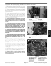
Power Shaft Bearing
Removal
1. Remove brake band from the counter shaft housing
(see Brake Band Removal)
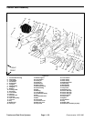
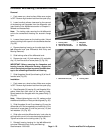
2. Remove cap screw (39) and lock washer (40) from
the front box cover (37) and counter shaft housing (1).
Remove cover from housing (Fig. 33).
3. Loosen cap screw (36) enough to rotate idler pulley
(44) away from the belt (35). Loosen belt by rotating the
idler pulley counterclockwise (Fig. 33).
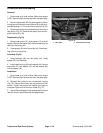
4. Remove three cap screws (36) and lock washers
(12) from the counter shaft housing (1) and bearing
housing (27). Slide the bearing housing off the power
shaft (57) (Fig. 33).
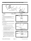
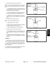
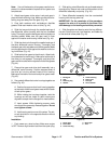
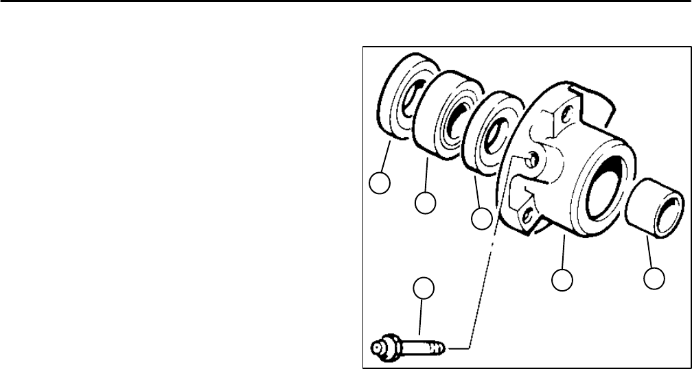
Disassembly (Fig. 36)
1. Pull short spacer from the inner seal and bearing
housing.
2. Pull outer seal, bearing, and inner seal from the
bearing housing.
Assembly (Fig. 36)
1. Press new seal with its flat side up through the
flange side of the bearing housing.
2. Press new bearing into the flange side of the bear-
ing housing.
3. Press second new seal with its flat side up through
the flange side of the bearing housing.
4. Push short spacer through inner seal until it con-
tacts the inner race of the bearing.
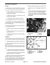
Installation
1. Park mower on a level surface. Make sure engine
is OFF. Remove high tension lead from the spark plug.
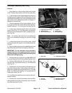
2. Slide the bearing housing onto the power shaft (57).
3. Secure three cap screws (36) and lock washers (12)
through the counter shaft housing (1) and into the bear-
ing housing (27) (Fig. 33).
4. Adjust idler pulley and differential belt tension. Rein-
stall front box cover (see Differential Belt in the Adjust-
ments section).
5. Reinstall brake band to the counter shaft housing
(see Brake Band Replacement Installation).
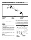
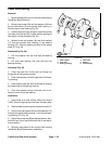
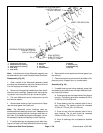
1. Short spacer
2. Inner seal
3. Bearing housing
4. Outer seal
5. Bearing
6. Grease fitting
Figure 36
4
2
5
1
3
6