


Greensmaster 1000/1600 Traction and Reel Drive SystemsPage 4 – 15
Drum Shaft Bearing
Removal
1. Remove drum drive belt from the drum drive assem-
bly (see Drum Drive Belt Replacement Removal).
Note: The pulley (LH) has left hand threads, while the
pulley (RH) has right hand threads. Each pulley has an
arrow stamped on it for the direction of tightening.
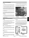
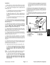
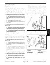
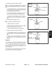
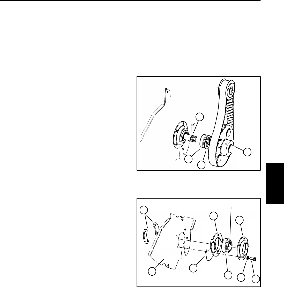
2. Remove pulley from drum shaft as follows (Fig. 22):
A. Use a suitable wrench on the flats of the drum
shaft, between the drum and the frame, to lock the
shaft.
B. Unscrew pulley from the drum shaft.
C. Remove backup washer and spacer from the
drum shaft.
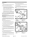
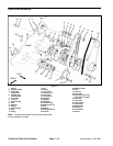
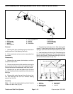
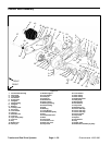
3. Remove bearing from drum shaft and frame as fol-
lows (Fig. 23):
A. Remove four cap screws and lock washers from
the flangettes, closure, frame, and bearing clamp.
B. Pull closure and flangettes with the bearing from
the frame and drum shaft.
C. Remove bearing from flangettes.
Installation
1. Park mower on a level surface. Make sure engine
is OFF. Remove high tension lead from the spark plug.
2. Install bearing to the drum shaft and frame as fol-
lows (Fig. 23):
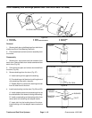
A. Place bearing between flangettes with the collar
on the bearing towards the flangette without the
grease fitting.
B. Insert two cap screws with lock washers through
the bottom holes of the flangettes. Place closure
onto capscrews. Secure assembly to frame with
bearing clamps.
C. Secure remaining cap screws with lock washers
through the flangettes and to the bearing clamps.
3. Install pulley to the drum shaft as follows (Fig. 22):
A. Apply loctite to the threads of the drum shaft.
B. Slide spacer and backup washer onto drum
shaft.
C. Use a suitable wrench on the flats of the drum
shaft, between the drum and the frame, to lock the
shaft. Screw pulley to the drum shaft.
4. Install drum drive belt to the drum drive assembly
(see Drum Drive Belt Replacement Installation).
5. Level drum to the reel (see Level Drum to Reel in the
Adjustments section of Chapter 7– Cutting Unit).
1. Drum shaft
2. Pulley
3. Backup washer
4. Spacer
Figure 22
2
4
3
1
1. Bearing
2. Frame
3. Cap screws
4. Lock washers
5. Flangette
6. Flangette (w\grease ftg)
7. Closure
8. Bearing clamp
Figure 23
5
6
7
3
4
1
8
2
BEARING COLLAR
Traction and Reel
Drive System