


Section 1
GENERATOR FUNDAMENTALS
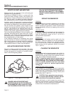
FIELD BOOST
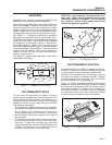
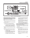
When the engine is cranked during startup, the
engine control circuit board Terminals 9, 10, and 11
(Wire 14) are energized with 12 VDC. Connected to a
Wire 14 is a resistor (R2) and a diode (D2). Battery
current flows through the 20 ohm 12-watt resistor and
the field boost diode D2, the voltage is reduced to 3-5
VDC. After passing through R2 and D2 it becomes
Wire 4 and current travels to the Rotor via brushes
and slip rings. This is called “Field Boost” current.
The effect is to “flash the field” every time the engine
is cranked. Field boost current helps ensure that suffi-
cient “pickup” voltage is available on every startup to
turn the Voltage Regulator on and build AC output
voltage.
NOTE: Loss of the Field Boost function may or
may not result in loss of AC power winding out-
put. If Rotor residual magnetism alone is suffi-
cient to turn the Regulator on, loss of Field Boost
may go unnoticed. However, if residual magnet-
ism alone is not enough to turn the Regulator on,
loss of the Field Boost function will result in loss
of AC power winding output to the load. The AC
output voltage will then drop to a value commen-
surate with the Rotor's residual magnetism (about
7-12 VAC).
GENERATOR AC CONNECTION SYSTEM
The generator set is equipped with dual stator AC
power windings. These two stator windings supply
electrical power to customer electrical loads by
means of a dual two-wire connection system.
Generators may be installed to provide the following
outputs:
1. 120/240 VAC loads — one load with a maximum total wattage
requirement equal to the generator’s rated power output, and
240 VAC across the generator output terminals; or two separate
loads, each with a maximum total wattage requirement equal to
half of the generator’s rated power output (in watts), and 120VAC
across the generator output terminals. Figure 1.9 shows the gen-
erator lead wire connections for 120/240 VAC loads.
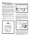
2. 120 VAC loads only — one load with a maximum total wattage
requirement equal to the generator’s rated power output (in
watts), and 120V across the generator output terminals. Figure
1.8 shows the generator lead wire connections for 120VAC
ONLY.
The generator set can be used to supply electrical
power for operating one of the following electrical
loads:
• QUIETPACT 75D: 120 and/or 240 VAC, single
phase, 60-Hertz electrical loads. These loads can
require up to 7500 watts (7.5 kW) of total power,
but cannot exceed 62.5 AC amperes of current at
120 VAC or exceed 31.2 AC amperes at 240 VAC.
CAUTION! Do not overload the generator.
Some installations may require that electrical
loads be alternated to avoid overloading.
Applying excessively high electrical loads may
damage the generator and may shorten its life.
Add up the rated watts of all electrical lighting,
appliance, tool and motor loads the generator
will power at one time. This total should not be
greater than the wattage capacity of the gener-
ator. If an electrical device nameplate gives
only volts and amps, multiply volts times amps
to obtain watts (volts x amps = watts). Some
electric motors require more watts of power (or
amps of current) for starting than for continu-
ous operation.
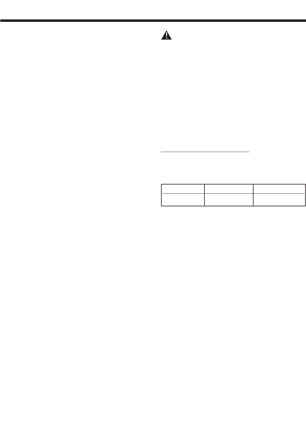
LINE BREAKERS (120 VAC ONLY):
Protects generator’s AC output circuit against
overload (i.e., prevents unit from exceeding
wattage/amperage capacity). The circuit breaker rat-
ings are as follows:
GENERATOR CONVERSION TO
120 VAC ONLY — DUAL CIRCUITS
NOTE: Conversion of a QUIETPACT™ generator
from "120/240 VAC dual voltage" to "120 VAC
only - dual circuits" (or vice-versa) requires
rerouting wires within the unit enclosure. It is rec-
ommended that this conversion be performed by
a Generac Authorized Service Dealer.
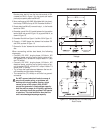
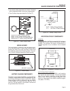
Figure 1-9 shows the stator power winding connec-
tions for 120 VAC only - dual circuits. Two stator
power windings are used, with each winding capable
of supplying half of the unit's rated wattage/amperage
capacity. The circuit from each winding is protected
against overload by a line breaker (CB1 and CB1A).
Line breakers CB1 and CB1A have a trip rating of 35
amps.
To convert from "120/240 VAC dual voltage" to "120
VAC only - dual circuits", disconnect battery power
from the generator and reverse stator lead Wires 33
and 44 as follows:
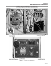
NOTE: It is necessary to feed stator lead Wires 33
and 44 through grommets on the electrical enclo-
sure and engine control box in order to perform
the rerouting outlined below. The front and top
unit enclosure panels, as well as the user control
panel, must be removed to perform this. After re-
routing, wires should be properly tied down to
prevent chafing or contact with moving internal
components
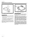
1. Remove stator lead Wire 33, as shown in Figure 1-8, from the
ground stud adjacent to the four-position terminal block.
Page 6
Model Circuit Breaker 1 Circuit Breaker 2
QuietPact 75D 35A 35A