


Section 7
DIAGNOSTIC TESTS
Page 43
RESULTS:
1. Replace the Rotor if it fails the test.
2. If Rotor checks good, perform “Insulation Resistance Test,” on
Page 14.
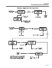
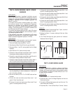
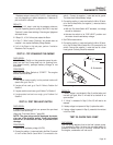
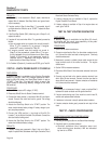
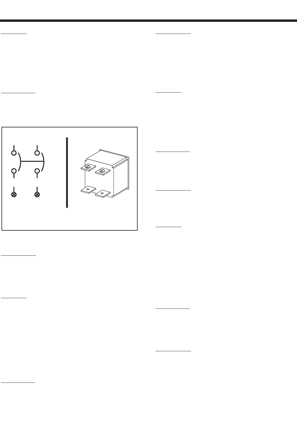
TEST 12 - CHECK MAIN CIRCUIT BREAKER
DISCUSSION:
The main circuit breaker on the generator panel must
be closed or no output to the load will be available. A
defective breaker may not be able to pass current
even though it is in the “ON” position.
Figure 7-8. – Main Breaker (Typical)
PROCEDURE:
Set the coach main breaker to it’s “OFF” position.
Check that the appropriate main breaker on the gen-
erator panel is set to its “ON” (closed) position. Set a
VOM to measure resistance and use it to check for
continuity across the breaker terminals.
RESULTS:
1. If breaker is “ON” and “Continuity” is measured, go to Test 3.
2. If breaker is “OFF”, reset to the “ON” position and check for AC
output.
3. If breaker is “ON” and “Continuity” is not measured, replace the
defective circuit breaker.
TEST 13- CHECK LOAD VOLTAGE &
FREQUENCY
DISCUSSION:
If engine speed appears to drop off excessively when
electrical loads are applied to the generator, the load
voltage and frequency should be checked.
PROCEDURE:
Perform this test in the same manner as Test 1, but
apply a load to the generator equal to its rated capac-
ity. With load applied check voltage and frequency.
Frequency should not drop below about 58 Hertz with
the load applied.
Voltage should not drop below about 115 VAC with
load applied.
RESULTS:
1. If voltage and/or frequency drop excessively when the load is
applied, go to Test 14.
2. If load voltage and frequency are within limits, end tests.
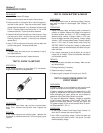
TEST 14- CHECK LOAD WATTS & AMPERAGE
DISCUSSION:
This test will determine if the generator's rated
wattage/amperage capacity has been exceeded.
Continuous electrical loading should not be greater
than the unit's rated capacity.
PROCEDURE:
Add up the wattages or amperages of all loads pow-
ered by the generator at one time. If desired, a clamp-
on ammeter may be used to measure current flow.
See “Measuring Current” on Page 16.
RESULTS:
1. If the unit is overloaded, reduce the load.
2. If load is within limits, but frequency and voltage still drop
excessively, complete Test 2, “Check/Adjust Engine Governor”.
If governor adjustment does not correct the problem, go to
Problem 8 (Flow Chart, Page 35).
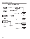
TEST 15 - CHECK BATTERY CHARGE
OUTPUT
DISCUSSION:
The Battery Charge system consists of a center tap
Battery Charge Winding, a Battery Charge Rectifier,
and a Battery Charge Resistor. During normal opera-
tion the battery charge output will vary between 1 to 2
amps, depending on the load applied to the generator.
PROCEDURE:
1. Disconnect Wire 15 from the Battery Charge Rectifier (center
terminal). Wire 15 is the fused battery supply.
2. Set a VOM to measure DC Amps. Connect the positive (+) test
lead to the center terminal of the Battery Charge Rectifier.
Connect the negative (-) test lead to Wire 15 previously discon-
nected.
3. Start the generator. The amp reading on the VOM should be
A.
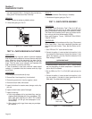
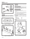
S
chemati
c
B. Pi
c
tori
al
C
B
1
T
3
44
T1
11
44A
11A