


Section 3
INSULATION RESISTANCE TESTS
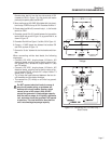
a. Across Wires No. 33 and 2.
b. Across Wires No. 11 (POWER) and 66.
c. Across Wires No. 33 and 66.
d. Across Wires No. 2 and 66.
If a breakdown in the insulation between isolated
windings is indicated, clean and dry the Stator. Then,
repeat the test. If the Stator fails the second test,
replace the Stator assembly.
TEST BETWEEN PARALLEL WINDINGS:
Connect the tester leads across Stator leads No. 11
(POWER) and 33. Apply a voltage of 1500 volts. If an
insulation breakdown is indicated, clean and dry the
Stator. Then, repeat the test between parallel wind-
ings. If the Stator fails the second test, replace it.
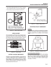
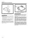
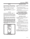
TESTING ROTOR INSULATION
To test the Rotor for insulation breakdown, proceed
as follows:
1. Remove the brush holders with brushes.
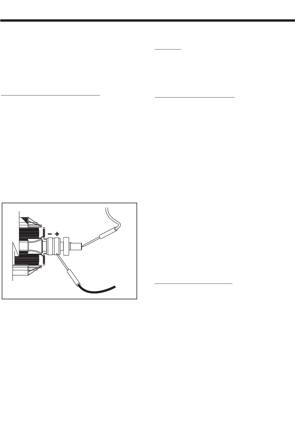
2. Connect the tester positive (+) test lead to the positive (+) slip
ring (nearest the Rotor bearing). Connect the tester negative (-)
test lead to a clean frame ground (like the Rotor shaft).
Figure 3-3. – Rotor Test Points
3. Apply 1000 volts. DO NOT APPLY VOLTAGE LONGER THAN
1 SECOND.
If an insulation breakdown is indicated, clean and dry
the Rotor then repeat the test. Replace the Rotor if it
fails the second test (after cleaning and drying).
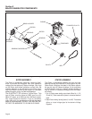
THE MEGOHMMETER
GENERAL:
A megohmmeter, often called a “megger”, consists of
a meter calibrated in megohms and a power supply.
Use a power supply of 1500 volts when testing
Stators; or 1000 volts when testing the Rotor. DO
NOT APPLY VOLTAGE LONGER THAN ONE (1)
SECOND.
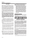
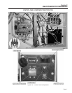
TESTING STATOR INSULATION:
All parts that might be damaged by the high megger
voltages must be disconnected before testing. Isolate
all Stator leads (Figure 3-2) and connect all of the
Stator leads together. FOLLOW THE MEGGER
MANUFACTURER'S INSTRUCTIONS CAREFULLY.
Use a megger power setting of 1500 volts. Connect
one megger test lead to the junction of all Stator
leads, the other test lead to frame ground on the
Stator can. Read the number of megohms on the
meter.
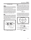
MINIMUM INSULATION
GENERATOR RATED VOLTS
RESISTANCE =
__________________________
+1
(in “Megohms”)
1000
The MINIMUM acceptable megger reading for Stators
may be calculated using the following formula:
EXAMPLE: Generator is rated at 120 VAC. Divide
“120” by “1000” to obtain “0.12”. Then add “1” to
obtain “1.12” megohms. Minimum insulation
resistance for a 120 VAC Stator is 1.12 megohms.
If the Stator insulation resistance is less than the cal-
culated minimum resistance, clean and dry the Stator.
Then, repeat the test. If resistance is still low, replace
the Stator.
Use the Megger to test for shorts between isolated
windings as outlined “Stator Insulation Resistance”.
Also test between parallel windings. See “Test
Between Parallel Windings”on this page.
TESTING ROTOR INSULATION:
Apply a voltage of 1000 volts across the Rotor posi-
tive (+) slip ring (nearest the rotor bearing), and a
clean frame ground (i.e. the Rotor Shaft). DO NOT
EXCEED 1000 VOLTS AND DO NOT APPLY VOLT-
AGE LONGER THAN ONE SECOND. FOLLOW THE
MEGGER MANUFACTURER'S INSTRUCTIONS
CAREFULLY.
ROTOR MINIMUM INSULATION RESISTANCE:
1.5 megohms
POSITIVE (+)
TEST LEAD
Page 14