


Section 5
ENGINE DC CONTROL SYSTEM
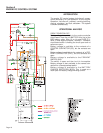
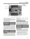
ENGINE CONTROL CIRCUIT BOARD
GENERAL:
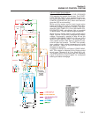
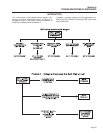
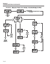
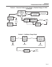
The ENGINE CONTROL circuit board is responsible
for cranking, startup, running, and shutdown opera-
tions. The board interconnects with other components
of the DC control system to turn them on and off at
the proper times. It is powered by fused 12 VDC
power from the unit battery.
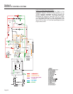
CIRCUIT BOARD CONNECTIONS:
The circuit board mounts two, six-wire terminal strips.
They are labeled 1-6 and 7-12.
The following chart shows the associated wires and
the function(s) of each terminal and wire.
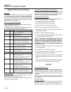
TERMINAL WIRE FUNCTION
1 15 Power supply (12VDC) for the circuit board
and DC control system.
2 0 Common Ground
3 17 To Start Stop Switch and remote connector.
When grounded by setting Start-Stop
Switch to "START", engine will crank.
4 18 To Start-Stop Switch and remote connector.
When grounded by setting Start-Stop-
Switch to "STOP", engine shuts down.
5 44 Frequency signal for overspeed
shutdown/starter disengage.
6 22 Frequency signal for overspeed
shutdown/starter disengage.
7 56 Delivers 12 VDC to Starter Contactor (SC)
while cranking only.
8 __ Not Used
9 14 Engine run circuit. Delivers 12 VDC during
cranking and running.
Connected to Fuel Pump, Fuel Solenoid,
Hourmeter, and field boost circuit.
10 14 Engine run circuit. Delivers 12 VDC during
cranking and running.
Connected to Fuel Pump, Fuel Solenoid,
Hourmeter, and field boost circuit.
11 14 Engine run circuit. Delivers 12 VDC during
cranking and running.
Connected to Fuel Pump, Fuel Solenoid,
Hourmeter, and field boost circuit.
12 85 Fault shutdown circuit. When grounded by
High Water Temperature or Low Oil
Pressure switch, engine will shut down.
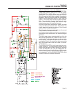
LED FUNCTIONS:
Green LED will be illuminated when Wire 14 is ener-
gized during cranking and running.
Red LED will be illuminated when Wire 56 is ener-
gized during cranking only.
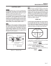
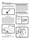
OVERSPEED SHUTDOWN POTENTIOMETER:
The overspeed shutdown potentiometer is used to set
the frequency at which the board will initiate a engine
shutdown. Proper setting of the potentiometer is criti-
cal to the correct operation of the generator.
ADJUSTMENT PROCEDURE:
The overspeed shutdown potentiometer MUST be
adjusted on replacement circuit boards.
If not replacing a board, start at STEP 6.
1. Remove 14 amp fuse (F1) from control panel.
2. Disconnect all wires from circuit board terminals.
3. Remove old circuit board and install new circuit board.
4. Connect all wires to proper circuit board terminals. Follow elec-
trical schematic if needed.
5. Reinstall 14 amp (F1) fuse into control panel.
6. Turn the overspeed shutdown potentiometer slowly counter-
clockwise until it stops. DO NOT FORCE.
Note: If immediate shutdown occurs when the
engine starts and the START/STOP switch is
released, reverse overspeed shutdown pot set-
ting, turn pot clockwise and proceed. In Step 10
and Step 11, turn the overspeed shutdown pot
counterclockwise.
7. Connect an accurate AC frequency meter across the genera-
tor's AC output leads.
8. Start the generator, let it stabilize and warm up.
9. Use the injection throttle lever to SLOWLY increase engine
speed until the frequency meter reads 64 hertz.
10. Hold the throttle at 64 hertz and SLOWLY turn the overspeed
shutdown potentiometer clockwise until engine shutdown
occurs.
11. Turn the overspeed shutdown potentiometer clockwise an
additional 1/8 turn. The overspeed setting is now correct.
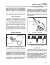
BATTERY
RECOMMENDED BATTERY:
When anticipated ambient temperatures will be con-
sistently above 32° F. (0° C.), use a 12 VDC automo-
tive type storage battery rated 70 amp-hours and
capable of delivering at least 360 cold cranking
amperes.
The QUIETPACT 75D generator is rated at about 160
DC Amps of cranking current to operate the starter
and glow plugs.
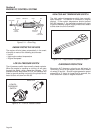
BATTERY CABLES:
Use of battery cables that are too long or too small in
diameter will result in excessive voltage drop. For
best cold weather starting, voltage drop between the
Page 24