


3. Set the VOM to measure resistance (“Rx1” scale). Connect
one meter test lead to Wire 0, Terminal 2 on the Engine
Controller Circuit Board. Connect the other test lead to a clean
frame ground.
“
Continuity” should be measured.
RESULTS:
1. If battery voltage is NOT indicated in Step 1, check continuity of:
a. Wire 13 between Starter Contactor and
Preheat Contactor.
b. Wire 13 between Preheat Contactor and 14
Amp Fuse (F1).
c. Wire 15 between the 14 Amp fuse (F1) and
the Battery Charge Rectifier.
d. Wire 15 between the Battery Charge
Rectifier and the Engine Controller Board.
Repair, reconnect or Replace bad wiring as necessary.
2. If battery voltage is indicated but engine will not crank, go to
Test 24.
3. If “Continuity” was not measured in Step 3, repair or replace
Wire 0 between the Engine Controller Circuit Board and the
Ground Terminal.
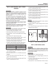
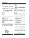
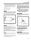
TEST 24 - CHECK START-STOP SWITCH
DISCUSSION:
Engine cranking and startup is initiated when Wire 17
from the Engine Controller board is connected to
frame ground by setting the Start-Stop Switch to
“START”.
Engine shutdown occurs when circuit board Wire 18
is connected to ground by the Start-Stop Switch.
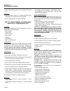
Figure 7-12. – Start-Stop Switch
A defective Start-Stop Switch can result in (a) failure
to crank when the switch is set to “START”, and/or (b)
failure to shut down when the switch is set to “STOP”.
PROCEDURE:
For Problem 6 (Section 6), perform all steps. For
Problem 9, perform Step 1 and Step 5 ONLY.
1. Set a VOM to its “Rx1” scale and zero the meter.
2. Inspect the ground Wire 0, between the Start-Stop Switch and
the grounding terminal. Connect one meter test lead to Wire 0
on SW1. Connect the other test lead to a clean frame ground.
“Continuity” should be measured.
3. Disconnect Wire 17 from its Switch terminal and connect it to
ground. The engine should crank.
4. Remove the 14 amp fuse. Disconnect Wire 18, Wire 0 and
Wire 17 from the Start-Stop Switch (SW1).
5. Connect one test lead to the center terminal of SW1. Connect
the other test lead to an outer terminal of SW1. “Infinity” should
be measured. Remove the test lead from the outer terminal of
SW1 and connect it to the opposite outer terminal. “Infinity”
should be measured.
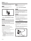
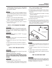
6. Leave the test lead connected to the center terminal of SW1
from Step 5. Connect the other test lead to an outer terminal.
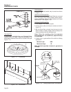
Depress the switch away from the terminal being tested (see
Figure 7-13). “Continuity” should be measured. Repeat the pro-
cedure with the test lead connected to the other outer terminal.
“Continuity” should be measured.
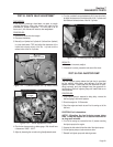
Figure 7-13. – Test 24, Step 6
NOT ACTIVATED
INFINITY
INFINITY
INFINITY
CONTINUITY
INFINITY
CONTINUITY
DEPRESSED
AWAY FROM
TERMINAL BEING
TESTED
DEPRESSED
AWAY FROM
TERMINAL BEING
TESTED
18
18
0
17
17
SW1
Page 47
Section 7
DIAGNOSTIC TESTS