


3. Set the Start-Stop Switch to “START.” During cranking only,
measure DC voltage. It should read 3-5 VDC. Reconnect Wire
4 to the Voltage Regulator. If voltage is measured, it can be
assumed that the Field Boost is working. Stop testing. If volt-
age is not measured, proceed to Step 4.
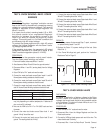
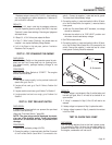
4. Test D2 diode: Place a VOM to measure continuity. Place one
test lead on one end of the diode and the other test lead on the
other end. Check for continuity, then reverse the leads and
retest. Continuity should only be measured in one direction,
and when it is measured, it should have a single beep and not
a constant tone. If continuity is measured in both directions
then the diode will need to be replaced. If diode tests good,
proceed to Step 5.
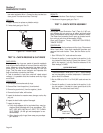
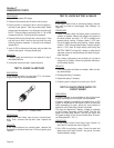
5. Test R2 resistor: Place a VOM to measure resistance.
Disconnect wires going to the terminals of the resistor. Place
the test leads on each terminal of the resistor. Resistance
should be 20 Ohms. If resistance is bad, replace the resistor.
If resistor is good, proceed to Step 6.
6. Test Wire 14: Place a VOM to measure continuity. Disconnect
Wire 14 from the R2 resistor. Unplug the BH2 connector.
Place one test lead on the Wire 14 end that was previously on
the resistor. Place the other test lead on Pin 7 of the BH2 con-
nector. Continuity should be measured. If wire is open,
replace it. If wire is good, disconnect Wire 14 from the circuit
board located on Terminal 11. Place one test lead on this end
and the other test lead on the other BH2 connector Pin 7.
Continuity should be measured. If continuity is not measured,
replace the wire. If continuity is measured, make sure that the
connection on BH2 is good. If the connection appears to be
good, then replace the circuit board.
RESULTS:
1. If field boost voltage checks good in step 3, than replace the
voltage regulator.
2. If field boost is not measured, replace failed parts in Steps 4-6.
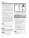
TEST 7 - TEST STATOR DPE WINDING
DISCUSSION:
An open circuit in the Stator excitation windings will
result in a loss of unregulated excitation current to the
Voltage Regulator. The flow of regulated excitation
current to the Rotor will then terminate and the unit's
AC output voltage will drop to a value that is equal to
the rotor’s residual magnetism (about 5 - 12 VAC).
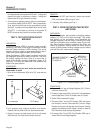
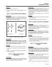
PROCEDURE:
1. Disconnect Wire 2 from the Excitation Circuit Breaker.
2. Disconnect Wire 6 from the Voltage Regulator.
3. Set a VOM to its “Rx1” scale and zero the meter.
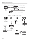
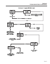
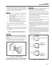
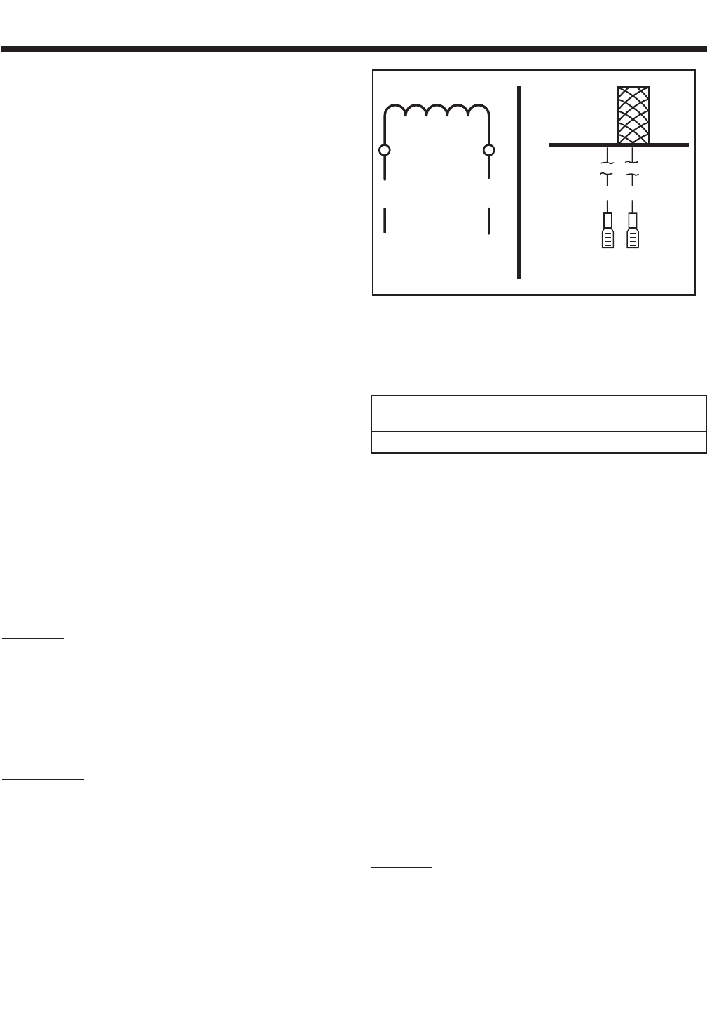
Figure 7-4. – Stator Excitation Winding
4. Connect the VOM test leads across the terminal ends of Wires
2 and 6. The VOM should indicate the resistance of the Stator
Excitation (DPE) Windings.
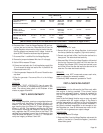
EXCITATION “DPE” WINDING RESISTANCE *
(Measured Across Wires 2 & 6)
MODEL QP75D 1.24 OHMS
* Resistance values in ohms at 20° C. (68° F.). Actual readings
may vary depending on ambient temperature. A tolerance of
plus or minus 5% is allowed.
5. Now, set the meter to its “Rx1 K” or “Rx10,000” scale and zero
the meter. Test for a “short-to-ground” condition as follows:
a.Connect one meter test lead to Stator lead No.
2, the other test lead to a clean frame ground.
b.The meter should read “Infinity”. Any other read-
ing indicates a “short-to-ground” condition and
the Stator should be replaced.
6. Test for a short between windings as follows:
a.Meter should be set to its “Rx1 K” or “Rx10,000”
scale.
b.Connect one meter test lead to Stator Wire 2,
the other test lead to Stator lead No. 11. The
meter should read “Infinity”.
c. Connect one VOM test lead to Stator lead No. 2
the other test lead to Stator lead No. 33.
“Infinity” should be indicated.
d.Connect one VOM test lead to Stator lead No. 2
and connect the other test lead to Stator lead
No. 66. “Infinity” should be indicated.
RESULTS:
1. If the Stator excitation (DPE) windings are open or shorted,
replace the Stator assembly.
2. If the excitation windings are good, perform “Insulation
Resistance Test”, page 13.
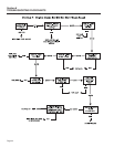
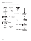
A.
S
chemati
c
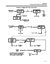
B. Pi
c
tori
al
226 6
Section 7
DIAGNOSTIC TESTS
Page 40