


Section 5
ENGINE DC CONTROL SYSTEM
Page 21
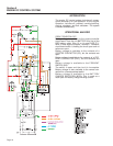
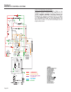
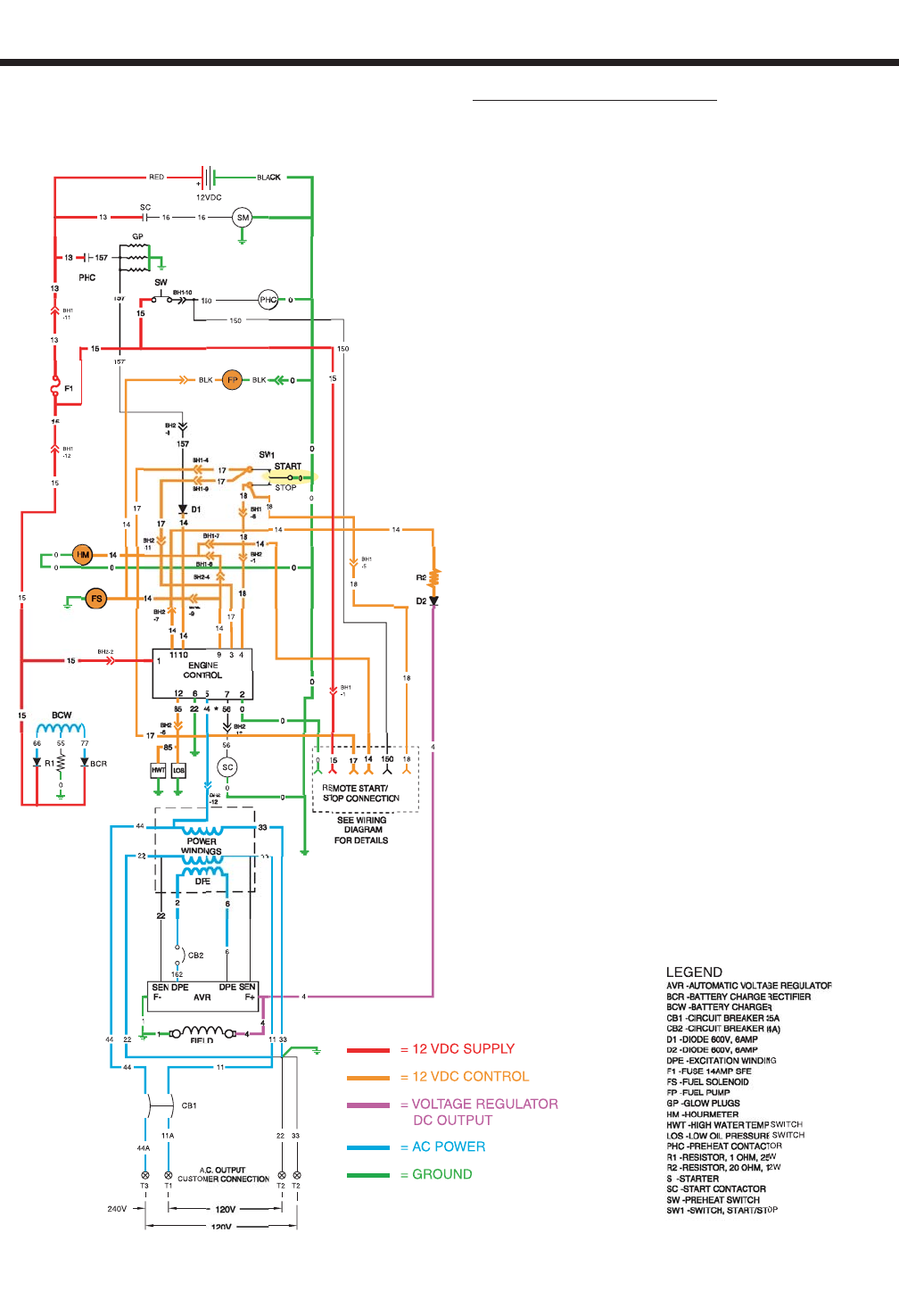
CIRCUIT CONDITION-RUNNING:
With the FUEL PUMP (FP) and FUEL SOLENOID
(FS) operating the engine should start. The START-
STOP SWITCH (SW1) is then released. Engine con-
trol circuit board action terminates DC output to the
STARTER CONTACTOR (SC), which then de-ener-
gizes the (SC) to end cranking.
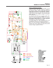
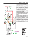
While running, engine control circuit board action
keeps Terminals 9, 10, and 11 energized which deliv-
ers battery voltage to the Wire 14 circuit. This ener-
gizes the FUEL PUMP (FP), FUEL SOLENOID (FS),
HOURMETER (HM), and optional light or hourmeter
in remote panel. This will maintain engine operation.
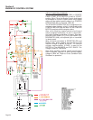
While running, engine control circuit board action
keeps Terminal 12 (Wire 85) energized with battery
voltage. Connected in parallel to Wire 85 are the
LOW OIL PRESSURE SWITCH (LOS) and HIGH
WATER TEMP SWITCH (HWT). The (LOS) has nor-
mally closed contacts. After start-up, engine oil pres-
sure will open the contacts. The HWT has normally
open contacts. High coolant temperature will close
the contacts. "Refer to Circuit Condition-Fault
Shutdown for operation".
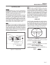
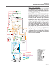
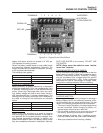
A voltage is induced into the Stator's POWER WIND-
ING. This voltage is delivered to the Engine control
circuit board Terminals 5 & 6 (via Wires 22 & 44).
The engine control circuit board uses this frequency
signal to determine engine speed for overspeed
sensing and starter disengage.