


Section 7
DIAGNOSTIC TESTS
6. Place test leads on each end of wire, continuity should be
measured.
7. If continuity is measured, test battery voltage on Wire 14 going
to circuit board on Pin 10, with prime switch pressed. Meter
should read battery voltage.
8. Set a VOM to measure resistance.
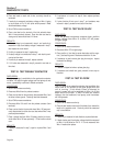
9. Place a test lead on the terminal of the fuel solenoid where
Wire 14 was previously located. Place the other test lead to
clean ground, meter should read 12.4 ohms.
RESULTS:
1. If battery voltage is not measured in step 4, and continuity is
measured in step 6 and battery voltage is measured in step 7,
than replace the circuit board.
2. If infinity is measured in step 6, replace wire.
3. If battery voltage is not measured in step 7, work back to previ-
ous test on flow chart.
4. If continuity is measured in step 9, replace solenoid.
5. If 12.4 ohms was measured in step 9, proceed to next test on
flow chart.
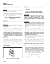
TEST 32- TEST PREHEAT CONTACTOR
DISCUSSION:
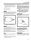
If battery voltage is available to the preheat contactor
via Wire 150 and the glow plugs and fuel pump do not
work, a possibility could be a failed contactor.
PROCEDURE:
1. Set a VOM to measure continuity.
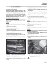
2. Disconnect Wire 0 from the preheat contactor.
3. Place one test lead on the previously disconnected Wire 0 and
the other to clean ground. Continuity should be measured.
4. Set a VOM to measure resistance.
5. Disconnect Wire 150 and 0 from the preheat contactor (front
terminals).
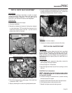
6. Place one test lead to the terminal where Wire 150 was previ-
ously disconnected, and the other test lead where Wire 0 was
previously disconnected.
7. Place a jumper lead from Wire 15 (battery positive) to the ter-
minal where Wire 150 was previously. Prime function should
occur.
RESULTS:
1. If infinity is measured in step 3, repair or replace Wire 0 and
retest.
2. If resistance is incorrect in step 6, then replace preheat
contactor.
3. If prime function did not occur in step 7, and resistance was
incorrect in step 6, proceed to next test on flow chart.
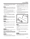
TEST 33- TEST GLOW PLUGS
DISCUSSION:
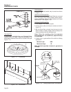
Once the preheat contactors contacts close, positive
battery voltage from Wire 13 to Wire 157 will power
the glow plugs.
PROCEDURE:
1. Set a VOM to measure resistance.
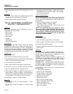
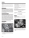
2. Disconnect Wire 157 from glow plugs.
3. Place positive (+) test lead to center electrode, and the nega-
tive (-) test lead to ground. Resistance should be 1.0 ohm.
4. If resistance is good, remove glow plug from engine. Inspect
the sheath for damage.
RESULTS:
1. If sheath is chipped or broken, replace glow plug.
2. If resistance and sheath are good, proceed to next step on
flowchart.
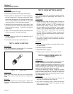
TEST 34- TEST D1 DIODE
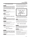
DISCUSSION:
The D1 diode is a protective device that prohibits the
return flow of DC current to the glow plugs while the
unit is running. If this diode is bad or shorted to
ground, power will not be available to Wire 14 off the
other end of the diode. If Wire 14 does not receive
voltage, the fuel solenoid, fuel pump, and hourmeter
will not operate.
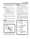
PROCEDURE:
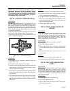
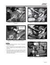
1. Set a VOM to measure continuity.
2. Place the test leads on each end of the diode, then reverse the
leads to the opposite ends. Continuity should be measured
only in one direction.
RESULTS:
1. If continuity is measured in both directions, replace the diode.
2. If diode checks good, then battery voltage should be measured
on Wire 14 to the board on Pin 10. If it is not measured, then
Wire 14 needs to be replace.
Page 52