


Section 5
ENGINE DC CONTROL SYSTEM
Page 20
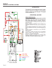
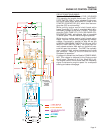
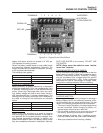
CIRCUIT CONDITION- CRANKING:
When the START-STOP-SWITCH (SW1) or REMOTE
PANEL START-STOP-SWITCH is held at "START"
position, Wire 17 from the Engine Control circuit board
is connected to Ground. Engine control circuit board
action will then deliver battery voltage to a STARTER
CONTACTOR (SC) via Terminal 7 Wire 56.
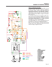
The STARTER CONTACTOR (SC) energizes and its
contacts close, battery output is delivered to the
STARTER MOTOR (SM) via Wire 16.The STARTER
MOTOR energizes and the engine cranks.
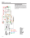
Also, while cranking, engine control circuit board
action energizes Terminals 9, 10, and 11 which deliv-
ers battery voltage to the Wire 14 circuit. This ener-
gizes the FUEL PUMP (FP), FUEL SOLENOID (FS),
HOURMETER (HM), and optional light or hourmeter
in remote panel.
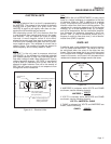
Wire 14 is also connected to RESISTOR (R2) and
DIODE (D2). After passing through R2 and D2
reduced voltage is applied to Wire 4. The reduced
voltage, approximately 3-5VDC, is sent to the
ROTOR via The BRUSHES and SLIP RINGS. This
voltage is used for Field Boost.
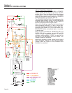
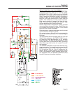
Also while cranking, engine control circuit board
action energizes Terminal 12 which delivers battery
voltage to Wire 85. "Refer to Circuit Condition-Fault
Shutdown for operation".