


Section 3
INSULATION RESISTANCE TESTS
DANGER!: DO NOT ATTEMPT TO WORK
WITH SOLVENTS IN ANY ENCLOSED AREA.
PROVIDE ADEQUATE VENTILATION WHEN
WORKING WITH SOLVENTS. WITHOUT ADE-
QUATE VENTILATION, FIRE, EXPLOSION OR
HEALTH HAZARDS MAY EXIST . WEAR EYE
PROTECTION. WEAR RUBBER GLOVES TO
PROTECT THE HANDS.
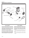
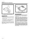
CLOTH OR COMPRESSED AIR:
For small parts or when dry dirt is to be removed, a
dry cloth may be satisfactory. Wipe the parts clean,
then use low pressure air at 30 psi (206 Kpa) to blow
dust away.
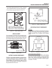
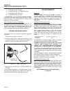
BRUSHING AND VACUUM CLEANING:
Brushing with a soft bristle brush followed by vacuum
cleaning is a good method of removing dust and dirt.
Use the soft brush to loosen the dirt, then remove it
with the vacuum.
STATOR INSULATION RESISTANCE
GENERAL:
Insulation resistance is a measure of the integrity of
the insulating materials that separate electrical wind-
ings from the generator's steel core. This resistance
can degrade over time due to the presence of conta-
minants, dust, dirt, grease and especially moisture.
The normal insulation resistance for generator wind-
ings is on the order of “millions of ohms” or
“megohms”.
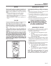
When checking the insulation resistance, follow the
tester manufacturer's instructions carefully. Do NOT
exceed the applied voltages recommended in this
manual. Do NOT apply the voltage longer than one
(1) second.
CAUTION!: DO NOT connect the Hi-Pot Tester
or Megohmmeter test leads to any leads that
are routed into the generator control panel.
Connect the tester leads to the Stator or
Rotor leads only.
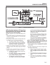
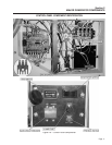
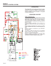
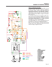
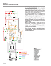
STATOR SHORT-TO-GROUND TESTS:
See Figure 3-2. To test the Stator for a short-to-
ground condition, proceed as follows:
1. Disconnect and isolate all Stator leads as follows:
a. Disconnect sensing leads 11 and 22 from
the voltage regulator.
b. Disconnect excitation winding lead No. 6
from the voltage regulator.
c. Disconnect excitation lead No. 2 from the
excitation circuit breaker (CB2).
d. Disconnect battery charge winding leads
No. 66 and 77 from the battery charge recti-
fier (BCR).
e. Disconnect battery charge winding lead No.
55 from the battery charge resistor (R1).
f. At the main circuit breakers, disconnect sta-
tor power leads No. 11P and 33.
g. At the ground stud (GND5), disconnect
Stator power leads No. 22 and 33.
2. When all leads have been disconnected as outlined in Step 1
above, test for a short-to-ground condition as follows:
a. Connect the terminal ends of all Stator leads
together (11, 22, 33, 44, 2,6, 55, 66, 77).
b. Follow the tester manufacturer's instructions
carefully. Connect the tester leads across
all Stator leads and to frame ground on the
Stator can. Apply a voltage of 1500 volts.
Do NOT apply voltage longer than one (1)
second.
If the test indicates a breakdown in insulation, the
Stator should be cleaned, dried and re-tested. If the
winding fails the second test (after cleaning and dry-
ing), replace the Stator assembly.
TEST BETWEEN ISOLATED WINDINGS:
1. Follow the tester manufacturer's instructions carefully.
Connect the tester test leads across Stator leads No. 11
(POWER) and No. 2. Apply a voltage of 1500 volts- DO NOT
EXCEED ONE SECOND.
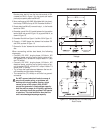
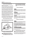
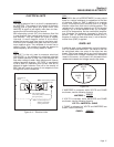
Figure 3-2. – Stator Leads
2. Repeat Step 1 with the tester leads connected across the fol-
lowing Stator leads:
2
6
11
11
22
22
33
44
66
55
77
Leads 2 & 6 =Stator Excitation Winding
Leads 11 & 22 = Voltage Sensing Leads
Leads 11 & 22, 33 & 44 = AC Power Windings
Leads 55, 66, 77 = Battery Charge Windings
Page 13