


Section 8
ASSEMBLY
4. Attach a hoist hook to the top lifting bracket attached to the
engine.
5. Slightly lift the engine to take pressure off of the block of wood.
6. Remove the bolts holding front cross member frame to the
engine.
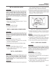
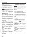
STARTER REMOVAL:
To get access to the starter for either testing or
removal, the unit will need to be lifted in order to
remove the bottom center panel. The battery will
need to be disconnected prior to removing the starter
if found to be faulty. The panel is held on by 2 latch-
es. Lift latches and remove lower panel. Remove
positive battery cable from the starter. Remove the 2
allen bolts mounting the starter to front cross member
frame. Remove starter.
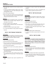
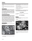
FUEL INJECTOR PUMP REMOVAL:
Prior to removing the injector pump, the top and side
panels will need to be removed. Remove rubber fuel
lines going to the brass fittings located at the top of
the fuel injector pump. CAUTION: Fuel is haz-
ardous. Disconnect Wire 14 going to the fuel sole-
noid that is mounted to the left of the fuel injector
pump. Remove the fuel solenoid by using a small
channel lock wrench and turn the solenoid counter
clockwise. Remove the metal fuel lines located at the
top of the fuel injector pump. Remove the other end
of the metal lines going to the nozzle injectors.
Remove the two retaining screws and two nuts hold-
ing injector pump to the governor assembly. Lift and
remove fuel injector pump and spacer shims.
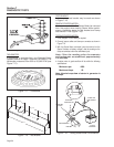
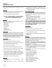
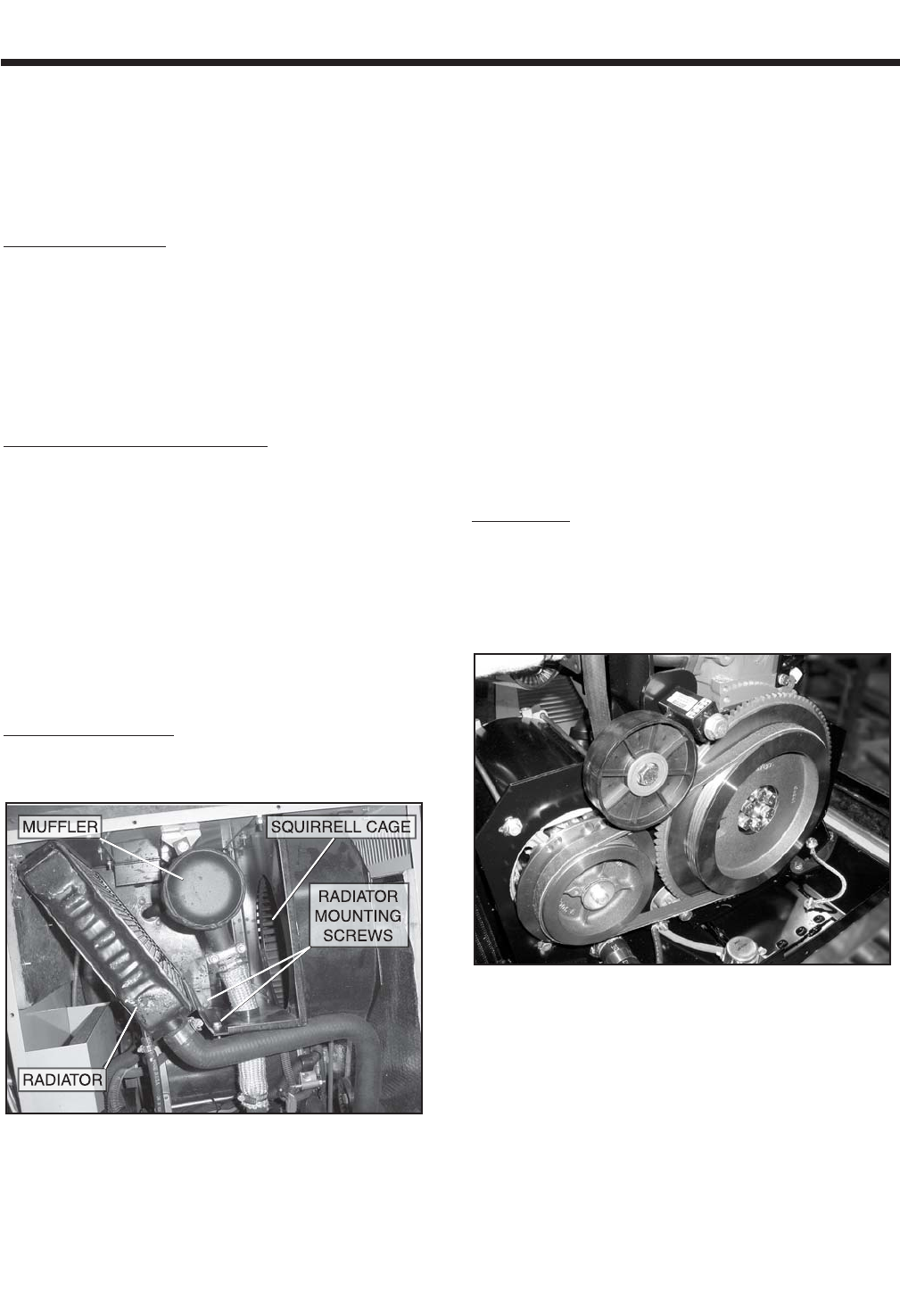
RADIATOR REMOVAL:
Prior to removing the radiator, the top panel will need
to be removed.
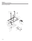
Figure 8-3. – Radiator Removal Points
1. Lift unit by engine lifting bracket to gain access to the bottom
hole under radiator.
2. Loosen drain plug and drain coolant into appropriate container
able to hold 1.4 gallons.
3. With the coolant drained, lower the unit and remove the lower
and 2 upper coolant hoses.
4. Remove the 4 screws and 2 nuts mounting the radiator to the
side panel and squirrel cage shroud.
5. Lift radiator out of unit.
When replacing the radiator, use a RTV sealant when
attaching the radiator hoses. When refilling the radia-
tor, use a 50/50 mixture of coolant and water.
RE-ASSEMBLY
To re-assemble the generator, reverse the previous
procedures.
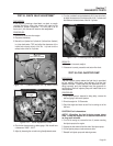
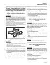
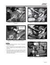
BELT TENSIONING
DRIVE BELT:
1. Install drive belt tensioner as shown in Figure 8-4. Snug mount-
ing bolt but do not tighten.
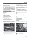
2. Using a 3/4” wrench, apply tension to the belt as shown in
Figure 8-5.
Figure 8-4. – Drive Belt Tensioner
3. Belt tension should be between 5-10° (see Figure 8-6). When
the proper tension is achieved, tighten the mounting bolt to
49 ft-lbs.
Page 58