


Section 2
MAJOR GENERATOR COMPONENTS
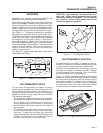
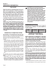
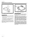
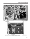
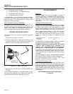
Figure 2-6. – Excitation Circuit Breaker
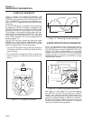
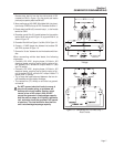
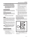
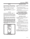
VOLTAGE REGULATOR:
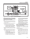
Six (6) leads are connected to the voltage regulator
as follows:
• Two (2) SENSING leads deliver ACTUAL AC out-
put voltage signals to the regulator. These are
Wires No. 11 and 22.
• Two (2) leads (4 and 1) deliver the regulated direct
current to the Rotor, via brushes and slip rings.
• Two (2) leads (No. 6 and 162) deliver Stator excita-
tion winding AC output to the regulator.
The regulator mounts a “VOLTAGE ADJUST” poten-
tiometer, used for adjustment of the pre-set REFER-
ENCE voltage. An LED will turn on to indicate that
SENSING voltage is available to the regulator and the
regulator is turned on.
Figure 2-7. – Voltage Regulator
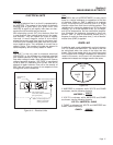
ADJUSTMENT PROCEDURE:
With the frequency set at 62.5-Hertz and no load on
the generator, slowly turn the voltage adjust pot on
the voltage regulator until 124 VAC is measured. If
voltage is not adjustable, proceed to Section 6 -
Troubleshooting.
NOTE: If, for any reason, sensing voltage to the
regulator is lost, the regulator will shut down and
excitation output to the Rotor will be lost. The AC
output voltage will then drop to a value that is
equal to Rotor residual magnetism (about 7-12
VAC). Without this automatic shutdown feature,
loss of sensing (actual) voltage to the regulator
would result in a “full field” or “full excitation”
condition and an extremely high AC output volt-
age.
NOTE: Adjustment of the regulator's “VOLTAGE
ADJUST” potentiometer must be done only when
the unit is running at its correct governed no-load
speed. Speed is correct when the unit's no-load
AC output frequency is about 62.5-Hertz. At the
stated frequency, AC output voltage should be
about 125 volts.
VOLTAGE
ADJUST POT
LED
11
22
4
1
6
162
1
62
2
Page 10