


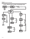
line voltage should read between 242-252 VAC. If voltage and
frequency are good, no adjustment is needed. If voltage and
frequency are low or high, proceed to next step.
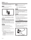
4. Turn the governor adjusting screws to obtain a no-load frequen-
cy as close as possible to 62-63 HERTZ. With no-load frequen-
cy set, apply an electrical load as close as possible to the unit's
rated load. Frequency with load applied should not fall below
58 HERTZ. If units frequency continues to drop below 58
HERTZ while under load, check for an overload condition.
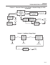
TEST 3- TEST EXCITATION CIRCUIT
BREAKER
DISCUSSION:
This circuit breaker (CB2) is normally closed and self-
resetting. It will open in the event of excessive current
from the Stator excitation (DPE) winding. The circuit
breaker should re-close or reset automatically after it
cools down (takes approximately two minutes).
When the breaker ( CB2) is open, excitation current to
the Regulator (and to the Rotor) will be lost. The unit's
AC output voltage will then drop to a value that is
equal to the Rotor's residual magnetism (about 5-12
volts AC). This test will determine if the breaker has
failed in its open position.
PROCEDURE:
Note: After running the unit, allow two minutes for
the breaker to reset.
1. Set a volt-ohm-milliammeter (VOM) to its “Rx1” scale and zero
the meter.
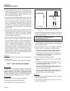
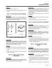
Figure 7-2. – Excitation “DPE” Circuit Breaker
2. In the generator panel, locate the excitation circuit breaker.
Disconnect Wire 2 and Wire 162 from the breaker terminals.
3. Connect the meter test leads across the two circuit breaker
(CB3) terminals. The meter should indicate “continuity”.
RESULTS:
1. If the meter did NOT read “continuity”, replace the excitation
(DPE) circuit breaker (CB2), and go to Test 4.
2. If “continuity” was indicated, go to Test 4.
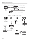
TEST 4- FIXED EXCITATION TEST/ROTOR
AMP DRAW
DISCUSSION:
The fixed excitation test consists of applying battery
voltage (12 VDC) to the Rotor windings. This allows
that portion of the excitation circuit between the
Voltage Regulator and the Rotor (including the Rotor
itself) to be checked as a possible cause of the prob-
lem. When battery voltage is applied to the Rotor, the
resulting magnetic field around the Rotor should
induce a Stator power winding voltage equal to about
one-half the unit's rated output voltage.
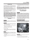
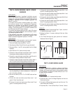
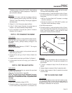
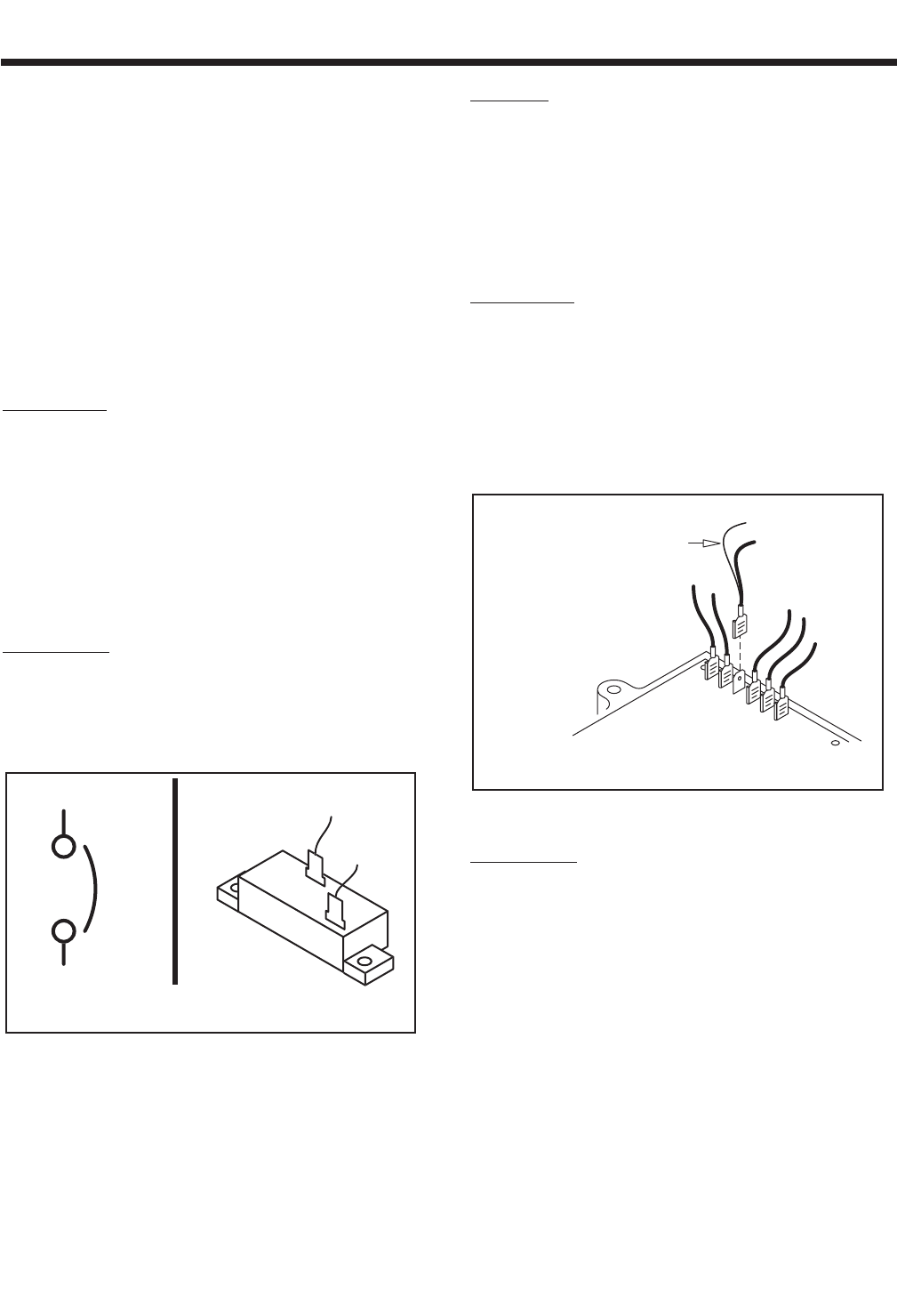
Figure 7-3. – Fixed Excitation Test
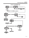
PROCEDURE:
1. Disconnect Wire 4 from the Voltage Regulator (VR). (Third ter-
minal from the top of VR).
2. Connect a jumper wire to Wire 4 and to the 12 volt fused battery
positive supply Wire 15 (Wire 15 located at fuse (F1) holder).
3. Set the VOM to measure AC voltage.
4. Disconnect Wire 2 from the DPE breaker (CB2) and connect
one test lead to that wire. Disconnect Wire 6 from the Voltage
Regulator and connect the other test lead to that wire. Start the
generator and measure the AC voltage. It should be above 60
VAC. Record the results and stop the generator.
5. Re-connect Wire 2 to the DPE Circuit Breaker (CB2) and re-
connect Wire 6 to the Voltage Regulator.
VOLTAGE
REGULATOR
TERMINALS
CONNECT POSITIVE (+)
BATTERY SUPPLY
TO WIRE #4
WIRE NO. 4
TO ROTOR
AND TO ECB
11
22
0
6
162
2A
2
C
B
3
2
A.
S
chemati
c
B. Pi
c
tori
al
2A
Section 7
DIAGNOSTIC TESTS
Page 38