


Section 7
DIAGNOSTIC TESTS
NOTE: For units out of warranty, refer to
Quicksilver Diagnostic & Service Manual - Diesel,
P/N 082034 for further engine service information.
This manual can be found at www.guardiangener-
ators.com, under “Brochures,Manual & Specs -
Recreational Vehicle - Manuals”.
TEST 38 - CHECK OIL PRESSURE SWITCH
DISCUSSION:
Also see “Operational Analysis” on Pages 18-23. The
Low Oil Pressure Switch is normally-closed, but is
held open by engine oil pressure during cranking and
startup. Should oil pressure drop below a safe level,
the switch contacts will close to ground the Wire 85
circuit. Engine controller board action will then initiate
an automatic shutdown.
If the switch fails CLOSED, the engine will crank and
start, but will then shut down after a few seconds.
If the switch fails OPEN, low oil pressure will not
result in automatic shutdown.
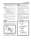
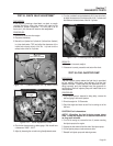
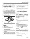
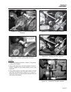
Figure 7-23. – Oil Pressure Switch
PROCEDURE:
1. Check engine oil level. If necessary, replenish oil level to the
dipstick “FULL” mark.
2. Set a VOM to its “Rx1” scale and zero the meter.
3. Connect the meter test leads across the switch terminals, with
engine shut down. The meter should read
“
Continuity”. A small
amount of resistance is acceptable.
4. Crank the engine. Oil pressure should open the switch contacts
at some point while cranking and starting. Meter should then
indicate “Infinity”.
5. If the contacts did not open in Step 5, remove the low oil pres-
sure switch and connect an oil pressure gauge in it’s place.
Start the engine and measure oil pressure. Pressure should be
above 10 psi.
RESULTS:
1. In Step 3, if “Continuity” is not indicated, replace the switch.
2. If oil pressure checked good in Step 5, but Step 4 measured
“Infinity,” replace the low oil pressure switch.
3. If oil pressure is below 10 psi, determine cause of low oil pres-
sure. Refer to Engine Service manual No. 0E2081 for further
engine service information. Verify that the oil is the proper vis-
cosity for the climate and season.
4. If all steps check GOOD, go to Test 40.
TEST 39- CHECK CIRCUIT BOARD FOR
GROUND
DISCUSSION:
If the engine shuts down immediately after start
switch is released, a possible cause would be the
ground wire is faulty, forcing the unit to ground the cir-
cuit board through the start/stop switch. Once the
switch is released, the ground is removed from the
board, causing the unit to shut down.
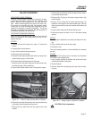
PROCEDURE:
1. Remove Wire 0 from the circuit board on Terminal 2.
2. Set a VOM to measure continuity.
3. Place one test lead on Wire 0, previously removed and the
other test lead on clean ground. Continuity should be mea-
sured.
4. Reconnect wire, making sure it has good contact on Pin 2 of
the circuit board.
RESULTS:
1. If continuity was not measured in step 3, replace wire.
2. If continuity was measured in step 3, replace the circuit board.
TEST 40- TEST WATER TEMPERATURE
SWITCH
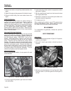
DISCUSSION:
This normally-open thermostatic switch has a sensing
tip, which is immersed in engine coolant. Should
coolant temperature exceed approximately 245-266
F, the switch contacts will close to ground Terminal
12 on the circuit board. Circuit board action will then
shutdown the engine.
PROCEDURE:
1. Disconnect Wire 85 from the switch terminal.
2. Set a VOM to measure continuity.
3. Place one test lead on switch and the other on clean ground.
Infinity should be measured.
Page 55