


Section 7
DIAGNOSTIC TESTS
Page 46
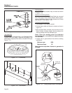
PROCEDURE:
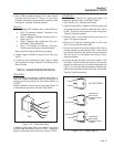
1. Set a VOM to measure DC voltage.
2. Disconnect the connector from the wires of the fuel pump.
3. Place the positive (+) test lead on Wire 14 and the negative (-)
test lead to clean ground. Press the pre-heat switch, battery
voltage should be measured, if not, disconnect the other end of
Wire 14. Place test leads on each end of Wire 14. Set a VOM
to measure continuity. Continuity should be measured.
4. Disconnect Wire 0 from the black wire of the fuel pump. Place
one test lead on Wire 0 and the other test lead to ground.
Continuity should be measured. If continuity is not measured,
replace Wire 0.
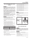
5. Jump 12 VDC to white wire of fuel pump, and jump black wire
to clean frame ground. Fuel pump should pump.
RESULTS:
1. If battery voltage and continuity are not measured in step 3,
then replace bad wire.
2. If pump does not pump in step 5, replace the pump
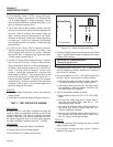
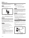
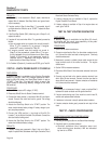
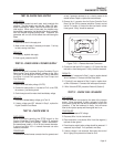
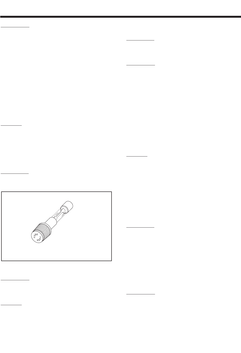
TEST 21- CHECK 14 AMP FUSE
DISCUSSION:
If the panel-mounted 14 amp fuse (F1) has blown,
engine cranking will not be possible.
Figure 7-11. – 14 Amp Fuse
PROCEDURE:
Push in on fuse holder cap and turn counterclock-
wise. Then, remove the cap with fuse. Inspect the
Fuse.
RESULTS:
If the Fuse element has melted open, replace the
Fuse with an identical size fuse. If Fuse is good, go to
Test 22.
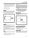
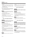
TEST 22- CHECK BATTERY & CABLES
DISCUSSION:
If the engine won't crank or cranks too slowly, the bat-
tery may be weak or discharged. See “Battery” on
Page 24.
PROCEDURE:
1. Inspect the battery cables and battery posts or terminals for
corrosion or tightness. Measure the voltage at the terminal of
the starter contactor and verify 11-12 VDC is available to the
generator during cranking. If voltage is below 11 VDC, mea-
sure at the battery terminals during cranking. If battery voltage
is below 11 VDC, recharge/replace battery. If battery voltage is
above 11 VDC, check for proper battery cable sizing (see
“BATTERY CABLES” on Page 24). If battery or cables are still
suspected, connect an alternate battery and cables to the gen-
erator and retest.
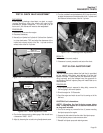
2. Use a battery hydrometer to test the battery for (a) state of
charge and (b) condition. Follow the hydrometer manufactur-
er's instructions carefully.
RESULTS:
1. Clean battery posts and cables as necessary. Make sure bat-
tery cables are tight.
2. Recharge the battery, if necessary.
3. Replace the battery, if necessary.
4. If battery is good, but engine will not crank, go to Test 23.
TEST 23- CHECK POWER SUPPLY TO
CIRCUIT BOARD
DISCUSSION:
If battery voltage is not available to the circuit board,
engine cranking and running will not be possible.
If battery voltage is available to the board, but no DC
output is delivered to the board's Wire 56 terminal
while attempting to crank, either the circuit board is
defective or the Start-Stop Switch has failed.
This test will determine if battery voltage is available
to the Engine Controller circuit board. Test 24 will
check the Start-Stop Switch. Test 25 will check the
DC power supply to the circuit board's Wire 56 termi-
nal (Receptacle J1, Pin 1).
PROCEDURE:
1. On the Engine Controller Circuit Board, locate Terminal 1 to
which Wire 15 connects (see chart on Page 24).
2. Set a VOM to read battery voltage. Connect the meter test
leads across circuit board Terminal 1 and ground. The meter
should read battery voltage.