


Section 5
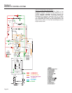
ENGINE DC CONTROL SYSTEM
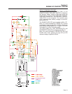
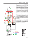
The positive (+) battery cable (13) attaches to one of
the outer posts of the contactor along with Wire 13 for
the DC supply to the fuse (F1). The starter cable (16)
attaches to the remaining outer post. Attached to the
small 2 lugs are Wires 56 and 0. When the start/stop
switch is set to start, the circuit board delivers battery
voltage to the contactor coil via Wire 56. The contac-
tor energizes and its contacts close. Battery voltage
is then delivered from the positive battery cable,
across contacts and to the starter motor via Wire 16.
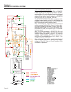
ENGINE GOVERNOR
A mechanical, all-speed governor is used on the
diesel engine. It is housed in the gear case. A fly-
weight movement is transmitted to the injection pump
control rack by way of the slider, control lever and
link. A spring is attached to the arm and the tension
lever. The spring regulates flyweight movement. By
changing the set angle of the governor lever, tension
on the tension lever spring is changed. In this man-
ner, engine speed can be regulated by the governor
lever.
The generators A/C output frequency is directly pro-
portional to engine speed. Low governor speed will
result in a reduced A/C frequency and voltage, and
high governor speed will produce an increased fre-
quency and voltage.
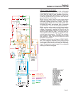
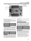
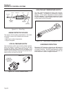
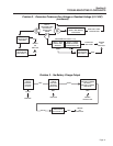
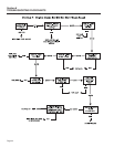
FUEL INJECTION PUMP
Figure 5-8. – Fuel Injection Pump
The fuel injection pump is mounted on the side of the
engine and rides on a three-lobe camshaft. The
lobes on the camshaft press the bottom of the pump,
which mechanically opens the fuel path to deliver fuel
to the fuel injectors. Timing for the fuel injector pump
is determined by the distance between the camshaft
lobes and the pump. This distance is regulated by
metal shims. If the shim space is incorrect, the fuel
pressure will be incorrect and combustion will not
occur. When the fuel injector pump is removed for
maintenance, be sure to reassemble with the same
number of shims. The engine governor controls the
fuel injector pump by linkage connecting the two.
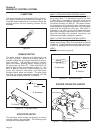
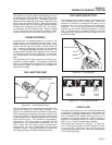
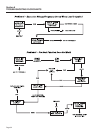
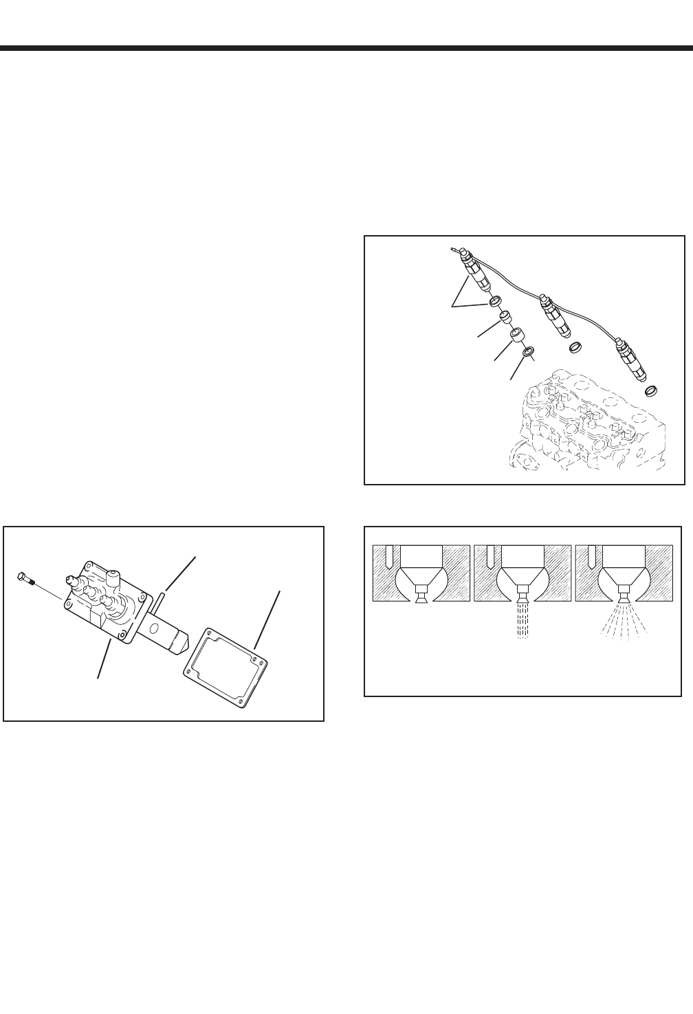
FUEL NOZZLES/INJECTORS
Fuel supplied by the injector pump is delivered to the
nozzle holder and to the nozzle body. When fuel
pressure is sufficient to compress the spring, fuel is
supplied from the nozzle and into the combustion
chamber. Due to the high pressure of fuel being
ejected from the nozzle, there is no safe test. If faulty
fuel is suspected and a clogged injector pump was
diagnosed, the replacement of the injector nozzles
would be needed.
Figure 5-9. – Fuel Injectors
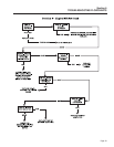
Figure 5-10. – Fuel Injector Nozzles
GLOW PLUGS
The glow plug consists of a thin coiled heat-wire that
is encased in sintered magnesium oxide powder and
enclosed by a stainless steel sheath. One end of the
wire is welded to the sheath and the other end is
welded to the center electrode. When voltage is
applied to the center electrode, it heats the heat-wire,
which in turn, heats the combustion chamber.
Glow plugs are connected in parallel. For that rea-
son, if one plug fails open, the other plugs will contin-
ue to operate. However, loss of one plug will
increase the possibility of the heat-wire melting open
in the remaining plugs.
VALVE
CLOSED
VALVE
OPEN
FULLY
OPEN
IN
J
E
C
T
OR
C
A
P
IN
S
ER
T
G
A
S
KE
T
CONTROL RACK
INJECTOR PUMP
SHIM
Page 27