


Section 7
DIAGNOSTIC TESTS
Page 37
INTRODUCTION
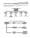
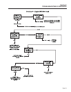
The “Diagnostic Tests” in this chapter may be per-
formed in conjunction with the “Flow Charts” of
Section 6. Test numbers in this chapter correspond to
the numbered tests in the “Flow Charts”.
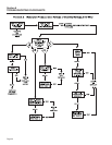
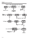
Tests 1 through 17 are procedures involving problems
with the generator's AC output voltage and frequency
(Problems 1 through 4 in the “Flow Charts”).
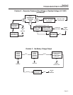
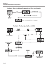
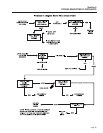
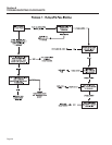
Tests 18 through 42 are procedures involving prob-
lems with engine operation (Problems 5 through 9 in
the “Troubleshooting Flow Charts”).
Review and become familiar with Section 4,
“Measuring Electricity”.
NOTE: Test procedures in this Manual are not nec-
essarily the only acceptable methods for diagnos-
ing the condition of components and circuits. All
possible methods that might be used for system
diagnosis have not been evaluated. If any diagnos-
tic method other than the method presented in this
Manual is utilized, ensure that neither personnel
safety nor the product's safety will be endangered
by the procedure or method utilized.
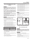
TEST 1- CHECK NO-LOAD VOLTAGE AND
FREQUENCY
DISCUSSION:
The first step in analyzing any problem with the AC
generator is to determine the unit's AC output voltage
and frequency.
PROCEDURE:
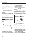
1. Set a volt-ohm-milliammeter (VOM) to read AC voltage.
Connect the meter test leads across customer connection
leads T1 (Red) and T2 (White).
2. Disconnect or turn OFF all electrical loads. Initial checks and
adjustments are accomplished at no-load.
3. Start the engine, let it stabilize and warm up.
4. Read the AC voltage.
5. Connect an AC frequency meter across AC output leads T1
(Red) and T2 (White) on the customer connection. Repeat the
above procedure.
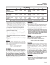
RESULTS:
For units rated 60-Hertz, no-load voltage and frequen-
cy should be approximately 122-126 VAC and 61-63
Hertz respectively.
1. If AC voltage and frequency are BOTH correspondingly high or
low, go to Test 2.
2. If AC frequency is good but low or residual voltage is indicated,
go to Test 3.
3. If AC output voltage and frequency are both “zero”, go to Test
12.
4. If the no-load voltage and frequency are within the stated limits,
go to Test 13.
NOTE: The term “low voltage” refers to any volt-
age reading that is lower than the unit's rated volt-
age. The term “residual voltage” refers to the out-
put voltage supplied as a result of Rotor residual
magnetism (approximately 5-12 VAC).
TEST 2 - CHECK & ADJUST
ENGINE GOVERNOR
DISCUSSION:
Rotor operating speed and A/C output frequency is
proportional. The generator will deliver a frequency of
60 HERTZ at 1950 RPM or 62 HERTZ at 2015 RPM.
The voltage regulator should be adjusted to deliver
120 VAC (line-to-neutral) at a frequency of 60 HERTZ
or 124 VAC (line-to-neutral) at 62 HERTZ. It is appar-
ent that if governor speed is high or low, A/C frequen-
cy and voltage will be correspondingly high or low.
Governor speed at no-load is usually set slightly
above the rated speed of 60HERTZ (to 62.8 HERTZ)
to prevent excessive RPM, frequency, and voltage
droop under heavy electrical loading.
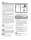
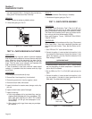
ENGINE GOVERNOR ADJUSTMENT:
Initial adjustment of governed speed should be
accomplished at no-load condition. Prior to engine
startup, turn off all electrical loads by whatever means
available (such as generator main circuit breaker).
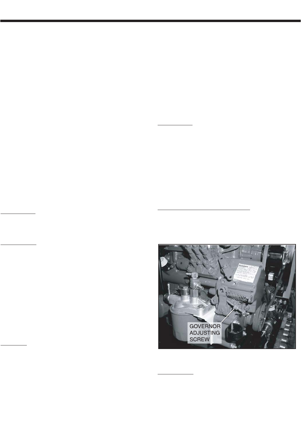
Figure 7-1. – Governor Adjustment Points
PROCEDURE:
1. Connect an accurate A/C frequency meter and voltmeter to the
proper generator leads.
2. Start the engine, let it stabilize and warm up at no-load.
3. Frequency meter should read between 62-63 HERTZ. Line-to-