


Section 7
DIAGNOSTIC TESTS
RESULTS:
1. If continuity is measure, replace the switch.
2. If infinity is measured, proceed to next test on the flow chart.
TEST 41- CHECK WIRE 14 AND CONNECTING
COMPONENTS FOR SHORT TO GROUND
DISCUSSION:
Once the start/stop switch is pressed, the circuit board
will take battery voltage from Wire 15 on Pin 1 and
provide it to Wires 14 on Pins 9,10,11. If Wire 14 or
any components attached to 14 are shorted to ground,
the 14-amp fuse will blow. This test will check the
wires and components in this cranking circuit.
PROCEDURE:
1. Set a VOM to measure continuity.
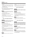
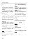
2. (Pin 9, Wire 14) Remove Wire 14 from Terminal 9, fuel sole-
noid, hourmeter, and fuel pump.
3. (Testing Wire 14 to ground) Place one test lead on Wire 14
(disconnected from the circuit board) and the other test lead on
clean ground. Meter should read infinity.
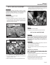
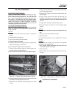
4. (Testing fuel solenoid to ground) If wire checks good but fuse
still blows when Wire 14 is connected, place one test lead on
the fuel solenoid where Wire 14 was connected. Place the
other test lead on clean ground. Fuel solenoid resistance
should be 12.4 ohms.
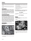
5. (Testing hourmeter to ground) Place on test lead on the
hourmeter where Wire 14 was previously connected. Place the
other test lead on clean ground. Infinity should be measured.
Hourmeter resistance should be 3.21 ohms.
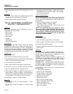
6. (Testing fuel pump to ground) Place one test lead on the fuel
pumps white wire. Place the other test lead on clean ground.
Infinity should be measured.
7. (Pin 10, Wire 14) Remove Wire 14 from Pin 10 on the circuit
board. Place one test lead on Wire 14, previously on Pin 10
and the other test lead on clean ground. Infinity should be
measured.
8. (Pin 11, Wire 14) See test 6 for testing field boost.
RESULTS:
1. If continuity was measured in Steps 3-6, replace faulty wires
are components.
2. If continuity was measured in Step 7, see test 34- testing D1
diode.
3. If Wire 14 and components check to be good, proceed to next
test on the flow chart.
TEST 42 - CHECK WIRE 56 AND STARTER
CONTACTOR FOR SHORT TO GROUND.
DISCUSSION:
Once the start/stop switch is pressed, the circuit
board will send battery voltage to Wire 56 to energize
the starter contactor in order for the starter motor to
crank the engine. If Wire 56 or the starter contactor is
shorted to ground, the 14-amp fuse will blow.
PROCEDURE:
1. Set a VOM to measure continuity.
2. (testing Wire 56 to ground) Disconnect Wire 56 from the circuit
board on Terminal 7 and from the starter contactor.
3. Place one test lead on one end of Wire 56 and the other test
lead to clean ground. Infinity should be measured.
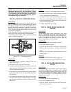
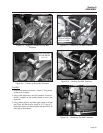
4. (testing starter contactor to ground) Place one test lead on ter-
minal where Wire 56 was previously connected and the other
test lead to clean ground. Infinity should be measured. Starter
contactor resistance should be 4.6 ohms (across the 2 small
terminals).
RESULTS:
1. If continuity was measured in steps 3 or 4, replace faulty wire
or starter contactor.
2. If no fault was indicated, proceed to next test on flow chart.
TEST 43 - CHECK WIRE 15 FOR SHORT TO
GROUND
DISCUSSION:
If Wire 15 is shorted to ground, the fuse will blow
immediately when replaced. This test will determine
if Wire 15 is bad.
PROCEDURE:
1. Set a VOM to measure continuity.
2. Disconnect Wire 15 from the fuse holder and from the battery
charge rectifier.
3. Place one test lead on Wire 15 (previously disconnected from
fuse) and place the other test lead to clean ground. Meter
should read infinity.
RESULTS:
1. If continuity was measured, replace bad wire.
2. If infinity was measured, proceed to next test on the flow chart.
Page 56